How to Wire a Switched GFCI Outlet: A Step-by-Step Guide
Answering Your Core Question: Wiring a Switched GFCI
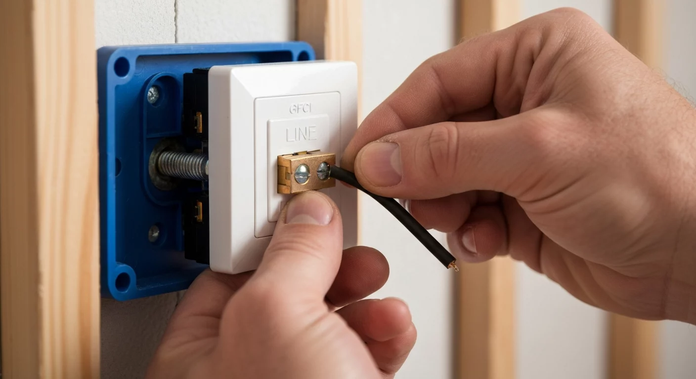
Wiring a switched GFCI outlet is done by switching the ungrounded (hot) conductor feeding the GFCI so that the entire GFCI device (and any downstream LOAD-protected devices, if used) is de-energized by the switch. Unlike a standard half-hot outlet, you cannot create a split-wired receptacle by breaking the brass tab on a GFCI; that is neither supported by the device nor compliant. The typical, code-compliant approach is to run the power feed to a switch first, place the incoming hot on one terminal of a single-pole switch, and run the switched hot from the other switch terminal to the GFCI. In the outlet box connect the switched hot to the GFCI’s LINE (hot) terminal and the neutral to the GFCI’s LINE (neutral) terminal — do not connect the supply to the LOAD terminals unless you intentionally want to extend GFCI protection downstream. This keeps switching in the ungrounded conductor as required by good practice and aligns with the GFCI-location requirements in NEC 210.8.
Understanding the “Why”: Applications for a Switched GFCI Outlet
As a licensed electrician, you know that installations must be not only compliant but also practical. A switched GFCI serves specific purposes where both ground-fault protection and switchable control are necessary. Common applications include controlling a garbage disposal from a countertop switch or providing switched control for specific equipment where both ground-fault protection and a switched disconnect are desired. In bathrooms, where the electrical code for bathroom receptacles is particularly stringent (GFCI protection is required for receptacles), a switched GFCI is used primarily for receptacles; ventilation fans and lighting are not generally required to be GFCI protected and are typically handled on their own circuits.
The National Electrical Code (NEC) continuously evolves to enhance safety. It’s critical to understand how these updates affect your work, especially in sensitive areas. For instance, recent 2023 NEC changes have impacted receptacle installation near bathtubs and showers, reinforcing the need for correct GFCI application in these zones.
Pre-Installation: NEC Compliance and Branch Circuit Design
Proper planning is the foundation of any professional electrical installation. Before you touch a single wire, review the project parameters against applicable NEC standards (including GFCI location rules and switch wiring requirements). This review includes site-specific branch circuit design, conductor sizing, box fill, and how the GFCI will be fed and whether it will protect downstream devices.
Safety First: De-energizing Circuits and Verification
The most critical step is the first one: de-energizing circuits you will be working on. Always shut off the corresponding breaker at the panel and apply a lock-out/tag-out device. Use a calibrated voltage tester or a multimeter to verify that the circuit is truly dead at every point of work—the switch box, the outlet box, and any related junctions. Never trust a switch or breaker position alone.
Code Considerations: NEC 210.8 and Beyond
The requirement for GFCI protection is primarily detailed in NEC 210.8, which outlines the specific locations where GFCIs are mandatory, including bathrooms, garages, kitchens, and any area near a water source. The NEC requirements for receptacles are clear, and a switched GFCI installation must adhere to these rules. It’s also wise to stay informed on broader code changes, such as the 2023 NEC island outlet requirements, as they reflect the code-making panel’s direction on residential power distribution and safety, often influencing requirements in other areas.
Planning Your Circuit: Conductor Sizing and Electrical Box Fill
Your branch circuit design must account for the load. Proper conductor sizing is non-negotiable—use 14 AWG conductors for 15-amp circuits and 12 AWG conductors for 20-amp circuits. You cannot install a 20‑amp receptacle on a 15‑amp circuit; on a 20‑amp general‑purpose branch circuit you may install 15‑amp or 20‑amp receptacles per NEC rules, but a single receptacle on an individual branch must have an ampere rating at least equal to the circuit rating. Furthermore, calculate your electrical box fill per NEC guidance to ensure you don’t overcrowd the box, which can lead to heat buildup and safety hazards.
The Core Difference: Why You Can’t Wire a Switched GFCI Like a Standard Half-Hot Outlet
In traditional residential wiring, creating a half-hot outlet (where the top outlet is switched and the bottom is always on) is a common request. This is accomplished by feeding the duplex receptacle with a 3-wire cable and breaking the brass tab connecting the two hot terminals. This effectively isolates them, allowing one to be connected to a constant hot and the other to a switched hot.
This method absolutely does not work for a GFCI receptacle. GFCI devices are internally a single, integrated electronic unit. They do not have a breakable tab to create a split-wired receptacle. Attempting to modify a GFCI in this way will destroy its internal mechanism and void its UL listing, creating a serious safety hazard. The only code-compliant way to create a switched GFCI outlet is to switch the entire power supply feeding its LINE terminals (i.e., switch the ungrounded conductor before it reaches the GFCI) so the whole device is de-energized by the switch.
Step-by-Step Guide: How to Wire a Switched GFCI Outlet
This guide details the most common method: switching the entire GFCI device on and off. Follow these steps meticulously, referencing this as your verbal switched GFCI wiring diagram.
- Confirm De-energization: Before starting, double-check that you are working on fully de-energizing circuits with a reliable voltage tester.
- Route Power to the Switch Box: Run your 2-wire-with-ground branch circuit feed (e.g., 12/2 for a 20A circuit) into the box designated for the single-pole switch.
- Execute Single-Pole Switch Wiring: Connect the incoming hot (black) wire to one of the brass terminals on the single-pole switch. Create a pigtail for neutrals if you need the neutral to continue through the box—neutrals should remain continuous and not switched. Bond all grounds together and attach a pigtail to the switch’s green screw.
- Run Cable to the GFCI Box: Route a 2-wire-with-ground cable from the switch box to the GFCI outlet box.
- Connect Switched Hot and Neutral: At the switch, connect the black wire from this new cable to the remaining brass terminal. This is your switched hot. At the GFCI outlet box, you will now have a switched hot (for LINE hot), a neutral, and a ground.
- Wire the GFCI LINE Terminals: Connect the switched hot (black) wire to the GFCI’s LINE hot terminal (brass). Connect the neutral (white) wire to the GFCI’s LINE neutral terminal (silver). If you plan to protect downstream devices, attach those downstream conductors to the LOAD terminals as directed by the device instructions — but do not swap LINE and LOAD.
- Ensure Grounding Integrity: Connect the ground wires in the outlet box with a pigtail and attach it to the green ground screw on the GFCI. Performing a grounding integrity check is a crucial safety measure. For older installations, knowing how to properly ground switches and receptacles is key to maintaining safety.
- Install and Test: Carefully fold the wires into the box, install the device, and attach the faceplate. Restore power at the breaker and test the installation. The GFCI outlet should only have power when the switch is in the ON position. Test the GFCI’s test and reset buttons to confirm functionality.
Leveraging GFCI Load Side Protection
One of the most powerful features of a GFCI is its ability to protect downstream devices. By connecting standard receptacles to the LOAD terminals of the GFCI, you extend ground-fault protection to them without the cost of additional GFCI devices. This is a highly effective strategy in branch circuit design, particularly for kitchen countertop circuits or in a garage. This concept of GFCI load side protection is separate from switching the GFCI itself but demonstrates the versatility of the device when using the GFCI line and load terminals correctly.
Perfect your residential wiring techniques with our hands-on guides.
Common Issues and Troubleshooting GFCI Trips
Even with a proper installation, issues can arise. Effective troubleshooting GFCI trips requires a systematic approach. Here are key considerations:
- Line/Load Reversal: The most common installation error is connecting supply to the LOAD terminals instead of LINE. If power is on the LOAD terminals, the GFCI will not reset or provide power.
- Downstream Ground Fault: If you are using the LOAD terminals, a ground fault in any connected appliance or downstream receptacle will cause the GFCI to trip.
- Shared Neutral: GFCIs cannot be used on multi-wire branch circuits (MWBCs) with a shared neutral unless the device or breaker is designed to monitor all ungrounded conductors simultaneously (for example a 2-pole GFCI breaker). A standard single‑receptacle GFCI will trip because of neutral imbalance on an MWBC.
- Device Failure: GFCIs have a limited lifespan and can fail internally. If the device won’t reset and you’ve confirmed correct wiring and no downstream faults, the GFCI itself may need replacement.
Primary Sources for Electrical Professionals
Always refer to the latest edition of the National Electrical Code for definitive guidance. You can access resources directly from the National Fire Protection Association (NFPA), the publisher of the NEC.
Frequently Asked Questions (FAQ)
- Can you make a GFCI a half-hot outlet by breaking the brass tab?
- No. A GFCI receptacle is an integrated electronic device. Unlike a standard duplex receptacle, it does not have a severable tab to create a split-wired receptacle. Attempting to modify a GFCI by breaking the brass tab will destroy the device and is a code violation.
- What are the basic NEC requirements for receptacles in a kitchen?
- The NEC requirements for receptacles in kitchens are extensive. As per NEC 210.8, GFCI protection is required for receptacles serving countertop surfaces and for receptacles within specified distances of sinks; spacing and location rules also apply, including rules for islands and peninsulas.
- How do you wire a switched GFCI to control a light while the outlet remains always on?
- This is a different configuration. You would bring the constant power feed directly to the GFCI LINE terminals. To control a separate light, you would pigtail from the incoming constant hot wire in the GFCI box to a single-pole switch. The switched leg from the switch would then run to the light fixture. In this setup, the switched GFCI outlet isn’t switched at all; it’s a constant-hot GFCI that happens to share a box with a switch controlling a different load.
Continuing Education by State
Select your state to view board-approved continuing education courses and requirements:
Disclaimer: The information provided in this educational content has been prepared with care to reflect current regulatory requirements for continuing education. However, licensing rules and regulations can vary by state and are subject to change. While we strive for accuracy, ExpertCE cannot guarantee that all details are complete or up to date at the time of reading. For the most current and authoritative information, always refer directly to your state’s official licensing board or regulatory agency.
NEC®, NFPA 70E®, NFPA 70®, and National Electrical Code® are registered trademarks of the National Fire Protection Association® (NFPA®)
You may also like

Colorado Electrical Licensing Requirements and Reciprocity Guide

Standby Generators in DE: Navigating Coastal Storm Regulations
