How to Wire Electric Baseboard Heaters: A Step-by-Step Guide
Quick Summary: Electric Baseboard Heater Wiring Explained
Proper electric baseboard heater wiring is a critical skill for licensed electricians, governed by NEC Article 424. The process typically involves installing a dedicated branch circuit for baseboard heaters; most permanent baseboard heaters are 240 V, although small 120 V units exist. Correctly performing a baseboard heater amperage calculation and sizing the conductors for continuous loads (conductors must have ampacity of at least 125% of the continuous load) is the first step to determining proper conductor and overcurrent protection. For instance, a 3,000-watt load on a 240 V circuit draws 12.5 A; sizing conductors to 125% for continuous operation gives 15.625 A. A 12 AWG copper conductor (20 A ampacity) is commonly used for that load, and a 20 A double-pole breaker is the typical overcurrent device, provided the installation meets the applicable termination temperature and listing requirements. The installation often involves running NM‑B cable from the panel to a double-pole line-voltage thermostat and then to one or more heaters when the location is dry; in damp, wet, or exposed locations use NMC, conduit, or other approved wiring methods. Adhering to the specific NEC requirements for electric heaters ensures a safe and compliant installation of this common type of fixed electric space heating equipment.
Understanding the Fundamentals of Electric Baseboard Heater Installation
As a professional electrician, you know that installing an electric baseboard heater is more than just connecting a few wires. It’s a precise task that demands a thorough understanding of load calculations, circuit protection, and the National Electrical Code (NEC). Whether you’re adding supplemental heat to a room, installing an electric garage heater, or setting up a primary heat source for a new addition, the principles remain the same. These units provide zonal heating, warming a specific room or area, which contrasts with other heating types. For example, they differ from small portable heaters that aren’t fixed in place, and from central heating systems like furnaces or heat pumps, which distribute heat throughout a structure. This guide will walk you through the essential steps and code requirements for a professional installation.
Foundational NEC Requirements for Electric Heaters
All installations of electric baseboard heaters fall under NEC Article 424, Fixed Electric Space-Heating Equipment. This article is your primary reference. The most crucial concept within it is that heating equipment expected to run for three hours or more is considered a “continuous load.” This classification is the foundation for all your calculations. The NEC requirements for electric heaters require that conductors serving continuous loads have ampacity of at least 125% of the continuous load (see the general continuous-load provisions elsewhere in the NEC). That rule applies whether you’re wiring a single unit or multiple electric heaters for garage spaces; always check the specific Article 424 installation and protection requirements for heaters as well.
Calculating Load and Sizing the Circuit Correctly
Accurate calculations are the hallmark of a professional electrician. For any electric heater for garage or home, getting the numbers right prevents nuisance tripping and, more importantly, fire hazards.
Step-by-Step Baseboard Heater Amperage Calculation
Follow this procedure for every installation to ensure your circuit is properly sized before you even touch a wire. This process is key to determining the correct breaker sizing for electric heat.
- Determine Total Wattage: Sum the wattage of all heaters that will be on the single circuit. For example, two 1,500-watt heaters equal a total load of 3,000 watts.
- Calculate the Operating Amperage: Use Ohm’s Law (Amps = Watts / Volts). For our 3,000-watt example on a standard 240v circuit wiring setup: 3000W / 240V = 12.5 A.
- Apply the Continuous Load Factor: This is the most critical step for derating circuit for continuous load. Size conductors so they have ampacity of 125% of the continuous load. In our example: 12.5 A × 1.25 = 15.625 A.
- Select the Breaker and Wire: The calculated conductor ampacity requirement of 15.625 A means a 12 AWG copper conductor (nominal 20 A ampacity in typical conditions) is commonly selected, and a 20 A double-pole breaker is typically used. Confirm the conductor temperature rating and the termination ratings, and apply any ambient- or grouping-related derating from Article 310 when required.
Choosing the Right Wire Gauge for Electric Baseboard Heater
Once you’ve determined the conductor ampacity requirement, selecting the wire gauge is straightforward in most dwellings: use 12 AWG copper for a 20 A branch circuit and 10 AWG copper for a 30 A branch circuit, consistent with conductor ampacity tables and termination temperatures. Always verify the NM-B cable ampacity ratings in NEC Table 310.16 and account for any ambient-temperature or multi-conductor adjustment factors. Properly sizing conductors is a key part of overall dwelling unit load calculations, a topic where the 2023 NEC has introduced important changes.
The Core Job: Electric Baseboard Heater Wiring Procedures
With calculations complete and materials selected, you can begin the physical installation. A clean, methodical approach is essential for a professional and safe outcome.
Installing the Dedicated Circuit for Baseboard Heaters
An electric baseboard heater typically requires its own dedicated branch circuit. Sharing a circuit with lighting or general-purpose receptacles is frequently impractical because of load limitations and the rules governing utilization equipment (see NEC 210.23). In particular, NEC provisions that limit the ampacity allowance for fixed (fastened-in-place) utilization equipment when other loads are supplied on the same branch circuit make sharing impractical for most heater installations; for that reason dedicated circuits are the norm. You will run an appropriately sized cable from a new double-pole breaker in the panel to the thermostat location. If the wiring route is through damp or exposed locations (for example in some garages or outdoors), use NMC, conduit, or another method listed for those locations instead of NM‑B.
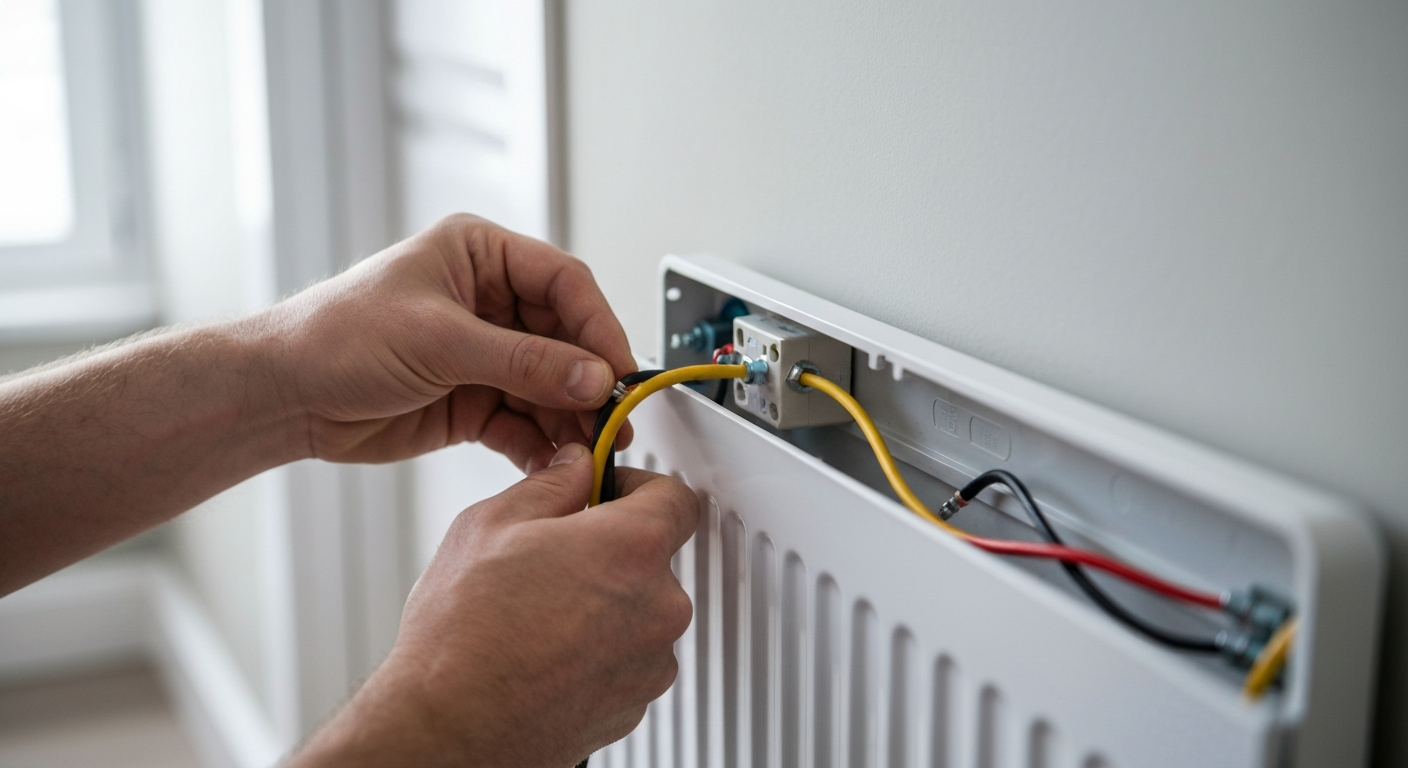
Thermostat Wiring for 240V Baseboard Heaters: A Guide to Double-Pole Installation
For 240 V heaters you must use a line-voltage thermostat appropriate for the load and location. A double-pole thermostat installation is the professional standard because it opens both hot legs (L1 and L2) and provides a complete disconnect. The line voltage thermostat wiring is direct:
- The two hot conductors from the panel connect to the thermostat “LINE” terminals (re-identify the white conductor if it is used as a hot leg).
- The two conductors going to the first heater connect to the thermostat “LOAD” terminals.
- The equipment grounding conductors are connected together and to the thermostat grounding terminal where provided.
Connecting Multiple Baseboard Heaters: End-to-End Wiring
Often, a single circuit will power multiple heaters in a large room or a garage heater electric setup. The process of connecting multiple baseboard heaters is done in parallel. The “load” wires from the thermostat feed the first heater. Inside that heater’s junction box, make connections to continue the circuit to the next heater. Follow the manufacturer’s end-to-end heater wiring diagram carefully. Ensure all splices are made within the heater’s junction box and that box fill is not exceeded. This is a common arrangement for an electric garage heater. Note that some garage heating appliances are 120 V and require their own calculations and wiring methods.
Important Safety and Compliance Considerations
A compliant installation goes beyond correct wiring. Pay close attention to these final details.
- Clearances: Heaters must be installed per their listing and manufacturer instructions; clearance requirements vary by unit and listing and must be observed for floors, walls, and adjacent combustible materials.
- AFCI/GFCI Protection: Requirements depend on the circuit and location: AFCI protection applies to many dwelling unit branch circuits (see NEC 210.12), and GFCI protection is required for receptacles in locations such as garages and basements (see NEC 210.8). Fixed heating equipment circuits are not automatically GFCI- or AFCI-protected solely because they feed a heater; consult the applicable NEC provisions and local amendments to determine protection requirements in each case. For guidance on how recent NEC changes affect AFCI/GFCI and heating-panel installations see how the 2023 NEC rules impact AFCI and GFCI protection for heating panels.
- Different Heating Types: Rules differ for other systems (for example, heating cables and in-wall panels). When working with radiant or cable systems consult the specific NEC guidance for those products; see how heating cable wall installations are addressed for an example of the different requirements.
- Device Identification: When a white conductor is used as an ungrounded conductor (as on many 240 V circuits without a neutral), re-identify it at each termination and at each accessible location where it is visible, using a durable marking method.
To truly master the nuances of the NEC and the wiring of fixed electric space heating equipment, continuous education is key. Master the wiring of fixed electric space heating equipment with our courses at ExpertCE.
Primary Sources for NEC Compliance
- National Fire Protection Association (NFPA) for the latest edition of the NEC (NFPA 70).
- Your specific state and local electrical licensing board for any amendments or local requirements.
Frequently Asked Questions (FAQ)
- What size breaker and wire do I need for an electric baseboard heater?
- The required breaker sizing for electric heat and the correct wire gauge for electric baseboard heater installation depend entirely on a load calculation. Sum the total wattage, divide by the voltage (usually 240 V) to get the amperage, and then size the conductors so that their ampacity meets at least 125% of the continuous load. This final number determines the minimum conductor ampacity, which in turn dictates the breaker and wire size (e.g., a 15.625 A conductor requirement typically leads to a 20 A breaker and 12 AWG conductor in typical dwelling conditions), subject to termination-temperature and derating rules.
- Can you explain the thermostat wiring for 240v baseboard heaters?
- The standard thermostat wiring for 240v baseboard heaters uses a double-pole, line-voltage thermostat. The two hot legs from the panel connect to the thermostat “LINE” terminals (L1, L2), and the two legs continuing to the heater connect to the “LOAD” terminals (T1, T2). A double-pole thermostat installation is recommended because it completely disconnects both ungrounded conductors for added safety.
- Is a dedicated circuit for baseboard heaters always required by the NEC?
- In most practical applications, yes. While the NEC does not have a single blanket rule that says “all baseboard heaters must have a dedicated circuit,” limitations on utilization equipment and continuous-load sizing (NEC 210.23 and related provisions) make sharing a general-purpose circuit impractical for most fixed electric heaters, so dedicated circuits are the common and safe practice.
- How does connecting multiple baseboard heaters work?
- Connecting multiple baseboard heaters on one circuit is done in parallel. Power is run from the thermostat to the first heater’s junction box, then on to the next heater, and so forth. Follow the manufacturer’s end-to-end heater wiring diagram, maintain proper junction-box fill, and ensure every splice and termination is accessible and handled in accordance with the NEC and the appliance listing.
Continuing Education by State
Select your state to view board-approved continuing education courses and requirements:
Disclaimer: The information provided in this educational content has been prepared with care to reflect current regulatory requirements for continuing education. However, licensing rules and regulations can vary by state and are subject to change. While we strive for accuracy, ExpertCE cannot guarantee that all details are complete or up to date at the time of reading. For the most current and authoritative information, always refer directly to your state’s official licensing board or regulatory agency.
NEC®, NFPA 70E®, NFPA 70®, and National Electrical Code® are registered trademarks of the National Fire Protection Association® (NFPA®)
You may also like

Colorado Electrical Licensing Requirements and Reciprocity Guide

Standby Generators in DE: Navigating Coastal Storm Regulations
