Understanding Traveler Wires in 3-Way & 4-Way Switch Setups
What Are Traveler Wires and How Do They Work?
In electrical wiring, traveler wires are the two conductors that run between 3-way and 4-way switches, creating a system for controlling a light or outlet from multiple locations. Unlike a standard single-pole switch, which simply opens or closes a circuit, a multi-way switching system uses travelers to provide two alternative pathways for electricity to flow. When a 3 way switch wiring setup is installed, one traveler wire is energized while the other is not, depending on the position of the first switch. The second switch then selects which traveler to draw power from to complete the circuit to the load. This is the core principle that allows either switch to independently control the light. For more complex setups, a 4 way switch can be inserted between the two 3-way switches, acting as a reversing switch for the travelers. Understanding the function of the common terminal versus the traveler terminal on a switch is crucial for any journeyman electrician or master electrician to wire these circuits correctly and safely.
The Fundamental Role of Traveler Wires in Multi-Way Switching
Traveler wires are essential conductors in any circuit that requires control from two or more points, but their function is often misunderstood. They do not directly power the light fixture. Instead, they act as messengers, carrying the potential to complete a circuit between switches. In a typical 3 way switch wiring scenario, you have four key conductors to manage:
- Constant Hot: This is the unswitched line conductor coming directly from the power source (breaker panel). It connects to the common terminal of the first 3-way switch.
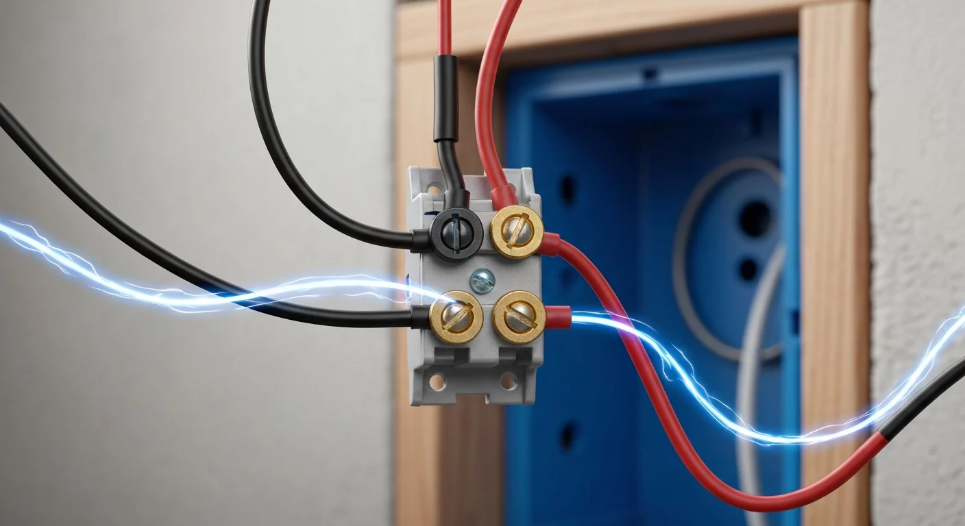
- Traveler Wires (x2): These two wires connect exclusively to the traveler terminal screws on each 3-way switch (and through any 4-way switches). Typically these are two of the colored conductors in a 3-conductor cable (commonly red and black, or red and a re-identified white). Colors can vary by installer; always verify conductor function rather than relying solely on color.
- Switched Hot (or Switch Leg): This conductor runs from the common terminal of the second 3-way switch to the light fixture or load. It only becomes energized when the switches are aligned to complete the circuit.
Think of the two traveler wires as two parallel roads. The first 3-way switch is a fork in the road, sending power down either Road A or Road B. The second 3-way switch is another fork that decides whether to accept power from Road A or Road B to continue the journey to the destination (the light fixture). This elegant system ensures either switch can change the state of the light.
Anatomy of a Switch: Common vs. Traveler Terminals
Correctly identifying the terminals on a multi-way switch is non-negotiable for a safe and functional installation. Unlike basic single-pole switches, 3-way and 4-way switches have distinct terminal arrangements.
3-Way Switch Terminals
A 3-way switch is technically a single-pole double-throw (SPDT) switch. It will always have three terminals for circuit conductors (plus a green ground screw):
- Common Terminal: This is the pivot point of the switch. It is usually identified by a darker-colored screw (often black or dark bronze). The constant hot feed connects to the common on the first switch, and the switched hot (switch leg) to the load connects to the common on the second switch.
- Traveler Terminals: These are two lighter-colored screws (typically brass or copper). The two traveler wires connect here. A common mistake is connecting a traveler to the common screw, which will prevent the circuit from operating correctly. For a visual reference, explore our 3-way switch wiring diagram guide.
4-Way Switch Terminals
A 4 way switch, or a double-pole double-throw (DPDT) reversing switch, is used between two 3-way switches to add more control points. It has four terminals (plus a ground) and no “common” terminal. These terminals are arranged in two pairs, often labeled “IN” and “OUT” or color-coded (e.g., two brass and two black screws). The two travelers from the first 3-way switch connect to one pair (e.g., the “IN” terminals), and the two travelers running to the next switch connect to the other pair (e.g., the “OUT” terminals). Flipping the toggle switch either passes the travelers straight through or crosses them, reversing their relationship and changing the state of the light. For more complex scenarios, see our detailed guide to wiring diagrams.
NEC Compliance and Proper Wire Identification
As a professional journeyman electrician or master electrician, adherence to the NEC (NFPA 70) is paramount. When dealing with traveler wires, several articles come into play, particularly concerning wire identification.
According to NEC 404.2, switching must be done only on ungrounded (hot) conductors. In many modern installations the code requires a grounded conductor to be available at specified switch locations (for example, switches controlling lighting loads). When a white wire is used as an ungrounded conductor in permitted situations, NEC 200.7(C) requires that conductor to be permanently re-identified at its terminations and at each location where the conductor is visible and accessible. Re-identification must be by a color other than white, gray, or green (black or red are commonly used). This practice prevents the dangerous assumption that the white wire is a neutral.
For a detailed breakdown of the process, you can learn how to wire a 3-way switch with our comprehensive guide, which covers code-compliant practices. Learning to correctly wire more complex setups, like understanding how to wire a 4 way switch, builds upon these fundamental NEC principles.
Troubleshooting Common Traveler Wire Issues
When a multi-way switching system fails, the problem often lies with the travelers. Issues can range from a simple loose connection to a more elusive traveler wire fault. Troubleshooting 4-way switch circuits follows the same logic, just with more components to check.
See these wires in action in our step-by-step 3-way switch wiring guide.
How to Perform Continuity Testing on Traveler Wires
One of the most reliable methods for diagnosing traveler issues is a continuity test. This test verifies that the wires have an unbroken path and are not shorted to ground.
- Safety First: De-energize the circuit at the breaker panel. Use a multimeter or non-contact voltage tester to confirm that power is off at all switches.
- Isolate the Travelers: At one of the 3-way switch locations, disconnect the two traveler wires from the switch terminals.
- Create a Loop: At the other switch location, disconnect the two travelers and twist them securely together with a wire nut. This temporarily creates a continuous loop for testing.
- Test for Continuity: Return to the first switch box. Set your multimeter to the continuity setting (it will beep or show a low resistance on a closed circuit). Touch one probe to each of the two disconnected traveler wires. The meter should indicate continuity, showing an unbroken path through the loop. If there is no continuity, there is a break (a traveler wire fault) in one of the wires.
- Test for a Ground-Fault: Untwist the wires at the second switch. Now, test each traveler individually to the bare copper ground wire in the box. The multimeter should not indicate continuity. If it does, it signifies a dangerous short circuit between the traveler and the equipment ground.
This process of continuity testing travelers is a core diagnostic skill for any electrician facing a faulty multi-way circuit.
Advanced Concepts and Field Considerations
Beyond basic wiring, experienced electricians encounter several advanced scenarios and phenomena in the field.
- Dead-End 3-Way: In this configuration, the power source feeds the light fixture box first, and a single 3-wire cable is run down to the switches. This creates a “dead-end” switch loop. Proper wire identification is critical here, as the white wire is often re-identified to carry the constant hot down to the first switch when this wiring method is used.
- Phantom Voltage: When using a high-impedance digital multimeter, you may detect a low voltage reading (e.g., 5-50V) on a traveler wire that should be de-energized. This is known as phantom voltage, caused by capacitive coupling from adjacent energized wires. It’s a normal phenomenon and does not have the power to energize a load or cause a shock. Using a low-impedance meter will typically eliminate these misleading readings.
- Code Updates and Education: The National Electrical Code is updated every three years. Requirements for neutrals in switch boxes and wire identification can change. Staying current with the latest NEC (NFPA 70) and reputable online electrical courses is essential for compliance and safety.
Primary Sources
- National Fire Protection Association (NFPA) for the National Electrical Code (NEC), NFPA 70, 2023 Edition.
Frequently Asked Questions (FAQ)
- What are traveler wires in a 3-way switch circuit?
- Traveler wires are two conductors that connect between two 3-way switches (and any 4-way switches in between). They provide alternate pathways for electricity, allowing the light to be controlled from multiple locations. They do not connect directly to the power source or the light fixture.
- Can a white wire be used as a traveler wire?
- Yes, within a cable assembly like 14/3 or 12/3 NM cable, a white wire can be used as a traveler when permitted by the NEC. However, when used as an ungrounded conductor it must be permanently re-identified at its terminations and at each accessible point where it is visible using a color other than white, gray, or green.
- How do I test for a traveler wire fault?
- To test for a break (a fault), de-energize the circuit, connect the two travelers together at one end, and check for continuity between them at the other end with a multimeter. To test for a short, check for continuity between each traveler and the ground wire; there should be none.
- What’s the difference between a common terminal and a traveler terminal?
- On a 3-way switch, the common terminal (usually a black screw) is the pivot. It’s where the constant hot connects on the first switch or where the switched hot to the load connects on the second switch. The two traveler terminals (usually brass screws) are only for connecting the traveler wires that run between the switches.
- Does a 4 way switch have a common terminal?
- No, a 4 way switch does not have a common terminal. It has four terminals arranged in two pairs (often labeled IN and OUT). It acts as a reversing switch for the traveler wires, either passing them straight through or crossing them to change the circuit’s state.
Continuing Education by State
Select your state to view board-approved continuing education courses and requirements:
Disclaimer: The information provided in this educational content has been prepared with care to reflect current regulatory requirements for continuing education. However, licensing rules and regulations can vary by state and are subject to change. While we strive for accuracy, ExpertCE cannot guarantee that all details are complete or up to date at the time of reading. For the most current and authoritative information, always refer directly to your state’s official licensing board or regulatory agency.
NEC®, NFPA 70E®, NFPA 70®, and National Electrical Code® are registered trademarks of the National Fire Protection Association® (NFPA®)
You may also like

Colorado Electrical Licensing Requirements and Reciprocity Guide

Standby Generators in DE: Navigating Coastal Storm Regulations
