Underground Service Conductors: NEC Article 230, Part IV
Underground Service Conductors: A Deep Dive into NEC Article 230, Part IV
Properly installing underground service conductors is a fundamental and critical task for any master or journeyman electrician. Governed by the National Electrical Code (NEC), specifically Article 230, these installations ensure a safe and reliable connection from the utility’s power grid to a building’s service equipment. Understanding the nuances of NEC Article 230, Part III and IV, is essential for compliance and safety. This involves correctly identifying the conductors, applying appropriate underground wiring methods, and ensuring adequate protection from physical damage. Key concepts include differentiating the service lateral from service-entrance conductors, selecting the correct insulation like Type USE conductors, and adhering to strict burial depth and protection standards outlined in NEC Table 300.5. From direct burial techniques to raceway installations, every step is guided by the NEC code book to ensure a durable and safe electrical service.
Understanding Underground Service Conductors (NEC 230)
Article 230 of the NEC is the cornerstone for all service installations, covering everything from the utility connection to the service disconnecting means. For underground services, Part III (Underground Service Conductors) and Part IV (Service-Entrance Conductors) are particularly relevant. Understanding the specific definitions laid out in Article 100 is the first step to correct application.
What is a Conductor? Service Lateral vs. Service Entrance Conductors
Before diving into installation rules, it’s crucial to know what is a conductor and to distinguish between different parts of the service. The term “underground service conductors” can be broken down into two main categories based on the location of the service point—the demarcation point between the utility’s responsibility and the property owner’s.
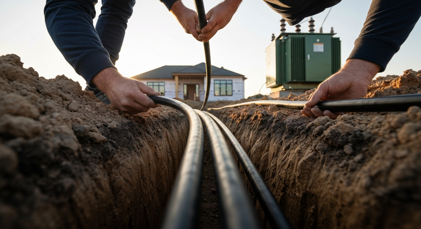
- Service Lateral: These are the underground conductors between the utility’s main supply (like a transformer) and the service point. Typically, the utility owns and maintains these conductors.
- Underground Service-Entrance Conductors: These are the conductors that run from the service point to the terminals of the service equipment (the main disconnect). These are the responsibility of the property owner and must be installed by a qualified electrician in strict accordance with the NEC. For more detail, you can review our guide on service entrance conductors per the NEC.
If the meter enclosure is located away from the building, the conductors from the service point to the meter are service laterals or underground service conductors, and the conductors from the meter to the building’s main disconnect are service-entrance conductors. This distinction is vital as it dictates which NEC rules apply. This article focuses on the requirements for the premises wiring portion, primarily the underground service-entrance conductors.
Key Regulations for Underground Wiring Methods (NEC 230.30)
NEC 230.30 specifies that underground service conductors must be insulated for the applied voltage. The NEC also provides a specific list of permitted underground wiring methods for these conductors. These methods are designed to protect the conductors from moisture and physical damage.
Conductor Types and Insulation (Type USE)
The most common type of cable used for underground services is Type USE (Underground Service Entrance). Type USE conductors are specifically identified in the NEC for direct burial or installation in raceways in wet locations. Products sold as USE are intended for that purpose; always confirm the manufacturer’s listing and the cable’s markings for temperature rating and permitted uses. SER and SEU are typically service-entrance constructions used above grade and should not be assumed suitable for direct burial unless the product listing explicitly permits it. For a broader look at different cable types, see this electrical cable types guide.
Raceway Installation vs. Direct Burial Methods
Electricians can install underground service conductors using two primary methods:
- Raceway Installation: Conductors can be pulled through a raceway, such as Rigid Metal Conduit (RMC), Intermediate Metal Conduit (IMC), or Schedule 80 PVC conduit. Using a raceway provides excellent physical protection and allows for easier replacement of conductors in the future. Note that certain wiring methods are listed for service-entrance use; consult Article 230 and the product listings for permitted applications.
- Direct Burial: Type USE conductors and other listed cables can be installed directly in the earth without a raceway. This method requires strict adherence to burial depths specified in NEC Table 300.5 to prevent damage from digging or other surface activities.
The choice between these methods depends on factors like cost, local soil conditions, and the potential for future physical damage. In either case, conductors must be protected from damage where they emerge from the ground, often by using a raceway such as Schedule 80 PVC or a short length of rigid conduit. While underground installations eliminate the aesthetic and clearance issues of overhead wires, they require meticulous planning to ensure long-term integrity. You can learn more about protecting conductors in our lesson on how open conductor installations are protected from physical damage. This contrasts with overhead installations, which have their own set of challenges, like those detailed in our article on how to install a service mast riser.
Sizing and Protection Requirements for Underground Service Conductors
Correctly sizing conductors and providing proper protection are paramount for a safe service installation. These steps ensure the system can handle the calculated load without overheating and is protected against faults.
Ampacity Calculations and the Wire Ampacity Chart
Conductor sizing for services is governed by NEC 230.42. The rule requires service conductors to have an ampacity adequate to carry the load being supplied. In practice, that means determining the building load per NEC Article 220 and then selecting conductor ampacity from the appropriate NEC tables (for example, the tables in Article 310) with any required temperature or adjustment factors applied. Factors like ambient temperature and the number of current-carrying conductors in a single raceway require ampacity adjustments.
Using a Voltage Drop Calculator for Performance
While ampacity tables ensure safety from overheating, they do not account for performance issues like voltage drop. For long underground runs, it is best practice to use a voltage drop calculator. The NEC provides informational guidance recommending limiting voltage drop to about 3% for branch circuits and 5% for the combined total of feeders and branch circuits to help ensure equipment operates efficiently. A significant voltage drop can cause motors to run hot, lights to dim, and electronics to malfunction. Sizing up the conductor is often the solution to mitigate excessive voltage drop.
Ensuring compliance with these detailed calculations is a hallmark of a professional installation. Ensure your service installations are flawless. Explore our NEC training for more in-depth online electrical courses.
Overcurrent and Fault Current Protection
The service disconnect (main breaker or fusible disconnect) is selected consistent with the ampacity of the service conductors and provides the required overcurrent protection. That service equipment must also have an interrupting rating equal to or greater than the available fault current at the installation. Ground-fault protection and short-circuit coordination involve additional NEC provisions and may require coordination with the supplying utility or other protective devices. Always ensure the interrupting ratings and protective-device selection match the available fault current and the equipment listings.
Installation Best Practices from NEC Table 300.5
NEC Table 300.5 is the definitive guide for the minimum cover requirements for underground wiring. “Cover” is defined as the distance from the top surface of the wire or raceway to the finished grade. The required depth varies based on the wiring method and the location.
Step-by-Step: Determining Burial Depth
- Identify the Location: Determine the location type from the rows in NEC Table 300.5. For example, is the installation under a building, under a street, or in a residential driveway?
- Identify the Wiring Method: Look at the columns in the table to find your wiring method. Column 1 is for direct-buried cables, Column 2 for Rigid Metal Conduit (RMC) or Intermediate Metal Conduit (IMC), and Column 3 is for nonmetallic raceways like PVC.
- Cross-Reference for Depth: The intersection of the location row and the wiring method column gives the minimum cover requirement. For example, direct-buried cable in a general location is commonly shown as 600 mm (24 in.), while the same circuit in rigid conduit in that location may show 150 mm (6 in.). Check the exact row and column that match your site conditions.
- Adjust for Conditions: Review the table notes for exceptions. For instance, if you encounter solid rock, the NEC allows alternatives such as concrete encasement and different cover depths under the conditions described in the table notes.
Critical Considerations for Installation
- Electrical Service Grounding: A proper grounding electrode system is required at the service. This is fundamental for safety, providing a path for lightning and high-voltage surges to dissipate.
- Conduit Fill: When using raceways, do not exceed the permitted fill percentages in NEC Chapter 9. Using a conduit fill calculator helps ensure you don’t overfill, which can cause heat buildup and make pulling conductors difficult.
- Backfill Material: The material used to backfill the trench must be free of large rocks or sharp objects that could damage the cable or raceway. Sand or fine earth is often used as the initial layer of backfill.
- Sealing Raceways: Where a raceway enters a building from underground, it must be sealed to help prevent moisture and soil gases from entering the structure.
- Warning Ribbon: For direct-buried conductors, an underground warning ribbon should be placed in the trench approximately 300 mm (12 in.) above the conductors to alert future excavators.
Frequently Asked Questions (FAQ)
What is the difference between service lateral and underground service conductors?
Service lateral conductors are typically owned by the utility and run from their main lines to the “service point,” which is the connection point to the premises wiring. Underground service conductors (specifically, service-entrance conductors) run from that service point to the main service disconnect of the building and are the property owner’s responsibility.
What does NEC 230.30 require for underground service conductors?
NEC 230.30 requires that underground service conductors be insulated for the applied voltage and lists permitted wiring methods for underground service conductors. For service-entrance conductors, Part IV lists specific permitted wiring methods for conductors entering the building; always consult Article 230 for the precise wiring-method lists and follow the product listings.
How do I perform conductor sizing for underground service conductors?
Conductor sizing is based on NEC 230.42 and the building load calculations in NEC Article 220. Calculate your loads, determine continuous and noncontinuous portions, apply the 125%/100% logic for continuous/noncontinuous where applicable, then select conductors from the ampacity tables in Article 310 (and apply any required temperature and adjustment factors). For long runs, a voltage drop calculator is also recommended.
What are the burial depth requirements from NEC Table 300.5?
The burial depths in NEC Table 300.5 vary by location and wiring method. For example, a general direct-buried cable may show 600 mm (24 in.) of cover in many locations, while the same circuit in Rigid Metal Conduit may require only 150 mm (6 in.) of cover in that same location. Always consult the table and notes for the precise requirements for your installation.
Continuing Education by State
Select your state to view board-approved continuing education courses and requirements:
Disclaimer: The information provided in this educational content has been prepared with care to reflect current regulatory requirements for continuing education. However, licensing rules and regulations can vary by state and are subject to change. While we strive for accuracy, ExpertCE cannot guarantee that all details are complete or up to date at the time of reading. For the most current and authoritative information, always refer directly to your state’s official licensing board or regulatory agency.
NEC®, NFPA 70E®, NFPA 70®, and National Electrical Code® are registered trademarks of the National Fire Protection Association® (NFPA®)
You may also like

Colorado Electrical Licensing Requirements and Reciprocity Guide

Standby Generators in DE: Navigating Coastal Storm Regulations
