Concrete-Encased Electrode (Ufer Ground) Rules in NEC 250.52
Understanding Ufer Ground Rules: A Deep Dive into NEC 250.52(A)(3)
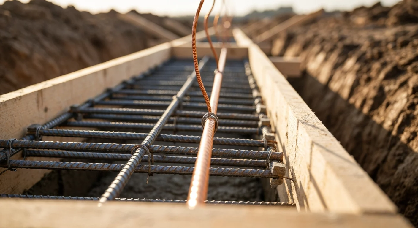
The Concrete-Encased Electrode (CEE), commonly known in the field as a “Ufer ground,” is a fundamental component of a modern grounding electrode system. The specific Ufer ground rules outlined in the nec code book under section NEC 250.52(A)(3) describe the construction details that qualify a footing or foundation for use as a concrete-encased electrode. These rules require at least 20 feet (6.0 m) of either 1/2-inch rebar or a bare #4 AWG copper conductor to be encased by at least 2 inches (50 mm) of concrete that is in direct contact with the earth. For any journeyman electrician or master electrician, understanding these requirements is critical for ensuring safety, passing an electrical inspection, and providing effective fault current dissipation. This type of electrode is often superior to a standard grounding rod, especially in areas with high soil resistivity.
What is a Ufer Ground (Concrete-Encased Electrode)?
The term “Ufer ground” is a trade name for what the National Electrical Code (NEC) officially calls a Concrete-Encased Electrode (CEE). This grounding method was developed during World War II by Herbert G. Ufer, a UL engineer, to solve significant grounding challenges at military installations in Arizona. He discovered that encasing a conductor in concrete created a highly effective and stable grounding electrode, superior to other methods, especially in soil with high resistivity.
The principle behind the CEE is that the large surface area of a building’s concrete foundation provides an excellent connection to the earth. Concrete retains moisture and contains minerals, which often makes the encased path more reliable than a single rod in some soils. By embedding a conductor within this concrete, you create a large, stable low-impedance path for fault currents to safely dissipate into the ground. Under NEC 250.50, all grounding electrodes present at a building must be bonded together, so a qualifying concrete-encased electrode is incorporated into the grounding electrode system when present.
The Mandatory Rule: NEC 250.52(A)(3) Explained
The core Ufer ground rules are found in section NEC 250.52(A)(3). Understanding every detail of this section is essential for any professional electrician, from a residential electrician to a master electrician working on large commercial projects. The code defines the specific construction and installation requirements for an electrode to qualify as a CEE.
Core Requirements for a Compliant CEE
To pass an electrical inspection, a concrete-encased electrode must satisfy several specific criteria. These requirements ensure the electrode is effective and durable. Here is a step-by-step breakdown of the NEC requirements:
- Conductor Material and Length: The electrode must consist of at least 20 feet (6.0 m) of one of the following:
- One or more bare, zinc-galvanized, or other electrically conductive coated steel reinforcing bars (rebar) of not less than 1/2 inch (13 mm) in diameter. If multiple pieces of rebar are used to achieve the 20-foot length, they must be connected together by steel tie wires, exothermic welding, welding, or other effective means.
- A bare #4 AWG copper conductor.
- Concrete Encasement: The conductor or rebar must be encased by a minimum of 2 inches (50 mm) of concrete. This encasement provides corrosion protection and ensures a solid electrical connection between the conductor and the surrounding concrete.
- Location within Concrete: The electrode must be located horizontally within the portion of a concrete foundation or footing that is in direct contact with the earth. It can also be located in a vertical foundation or structural component that is in direct contact with the earth.
- Direct Earth Contact: The concrete foundation or footing containing the electrode must be in direct contact with the earth. If the concrete is completely isolated from the soil by a continuous impermeable barrier, it will not meet NEC’s “direct contact” requirement and will not qualify as a CEE.
The “Direct Contact with Earth” Challenge
A persistent conflict for electricians is the “direct contact with earth” rule. Modern building and energy codes often require vapor barriers to be installed under concrete slabs and footings to control moisture. Where a continuous vapor barrier isolates the entire footing from soil contact, the footing does not qualify as a concrete-encased electrode under NEC 250.52(A)(3). This issue highlights the need for a journeyman electrician to coordinate with the general and concrete contractors early in the construction process. If a vapor barrier is present under the entire footing, the CEE cannot be used and other electrodes must be installed or the foundation detail modified to provide direct contact with the earth.
Sizing the Grounding Electrode Conductor (GEC) for a Ufer Ground
The grounding electrode conductor (GEC) is the conductor that connects the grounded service conductor (neutral) at the service equipment to the concrete-encased electrode or other grounding electrodes. The general rules for sizing this conductor are found in NEC 250.66, with an important exception that applies to concrete-encased electrodes.
NEC contains a specific allowance for concrete-encased electrodes: when the grounding electrode conductor portion that is the sole connection to a concrete-encased electrode does not extend on to other electrodes requiring larger conductors, that portion is not required to be larger than #4 AWG copper. That wording applies to the part of the conductor used solely for the connection into the concrete electrode; it does not eliminate the need to size other portions of the grounding electrode conductor where other Code rules or additional electrodes require larger conductors. For more detailed guidance on GEC calculations, our guides on NEC 250.66 conductor sizing and the 2023 updates to GEC sizing provide in-depth analysis. You can also explore specific examples in our article on sizing with NEC Table 250.66.
Ufer Ground vs. Grounding Rods: Key Differences
While a driven grounding rod is a common electrode, the Ufer ground offers distinct advantages. The primary benefit of a CEE is its massive surface area in contact with the earth via the concrete, which typically results in a much lower resistance to ground compared to a single grounding rod. This is especially true in areas with high soil resistivity, such as sandy or rocky terrain.
An important NEC distinction is that all grounding electrodes present at a structure are to be bonded together as part of the grounding electrode system; a qualifying concrete-encased electrode is one of those electrodes. A concrete-encased electrode that meets the criteria of 250.52(A)(3) normally supplies the grounding-electrode function without needing to be supplemented by another electrode. By contrast, a single driven grounding rod usually requires a second electrode unless its resistance to earth is shown to be 25 ohms or less. For more on this, see our guide on how to properly install a grounding rod.
Installation Best Practices and Electrical Inspection Tips
A successful CEE installation that passes electrical inspection the first time requires planning and attention to detail. This involves understanding not just the electrode itself, but also related components like the main bonding jumper and general bonding jumper requirements. When asked, “bonding what is it?” an expert knows it’s the electrical connection of all metallic parts to form a continuous conductive path.
This level of detail is critical for any residential electrician or commercial journeyman electrician. To truly master the grounding electrode system and other complex topics, professionals rely on quality electrician training. Master the grounding electrode system with our comprehensive NEC courses. You may also find the state-approved online electrical courses designed for licensed professionals helpful.
Key Considerations for Installation:
- Inter-Trade Coordination: Communicate with the concrete contractor before the pour. Confirm the absence of a continuous vapor barrier under the footing or plan for an exposed connection that meets accessibility and Code requirements.
- Proper Connection: The connection of the GEC to the rebar must be made with a listed and approved clamp suitable for direct burial or by exothermic welding; these methods are explicitly allowed by the Code.
- Accessibility: While the electrode itself is inaccessible after the pour, the point of connection for the GEC should be accessible where practical. The Code allows certain rebar extensions to be brought to an accessible location for termination.
- Continuity: If using rebar sections, ensure they are tied securely with steel tie wire, exothermic welding, or other effective means to create the continuous 20-foot conductive path that the Code requires. An inspector may ask how continuity was established.
- Corrosion Protection: The 2-inch concrete cover provides corrosion protection for the embedded conductor or rebar. Ensure any above-grade or exposed connections are protected from physical damage and corrosion.
Frequently Asked Questions (FAQ)
What are the primary Ufer ground rules in the nec code book?
The primary rules in NEC 250.52(A)(3) state that a Concrete-Encased Electrode must consist of at least 20 ft (6.0 m) of 1/2-in. reinforcing or equivalent, be encased in at least 2 in. (50 mm) of concrete, and be located where the concrete is in direct contact with the earth.
Is a #4 AWG copper conductor always the right size for a CEE grounding electrode conductor?
NEC 250.66 includes an allowance that the portion of the grounding electrode conductor that is the sole connection to a concrete-encased electrode need not be larger than #4 AWG copper. That is an exception for that specific portion; other parts of the grounding electrode conductor or other electrode connections may still require larger sizes under the Code.
Can I use a Ufer ground if there is a vapor barrier under the foundation?
Generally, no. The Code requires the concrete footing to be in “direct contact with the earth.” If a continuous vapor barrier isolates the footing from the soil, the footing does not qualify as a concrete-encased electrode and other electrodes will be required.
Does a rebar grounding electrode require supplemental electrodes like a grounding rod does?
No. A properly installed single Concrete-Encased Electrode that meets NEC 250.52(A)(3) is acceptable as part of the grounding electrode system; it does not automatically require a supplemental electrode the way a single driven rod typically does unless other conditions in the Code apply.
Continuing Education by State
Select your state to view board-approved continuing education courses and requirements:
Disclaimer: The information provided in this educational content has been prepared with care to reflect current regulatory requirements for continuing education. However, licensing rules and regulations can vary by state and are subject to change. While we strive for accuracy, ExpertCE cannot guarantee that all details are complete or up to date at the time of reading. For the most current and authoritative information, always refer directly to your state’s official licensing board or regulatory agency.
NEC®, NFPA 70E®, NFPA 70®, and National Electrical Code® are registered trademarks of the National Fire Protection Association® (NFPA®)
You may also like

Colorado Electrical Licensing Requirements and Reciprocity Guide

Standby Generators in DE: Navigating Coastal Storm Regulations
