Locating the Main Bonding Jumper: NEC Article 250 Rules
Locating the Main Bonding Jumper: NEC Article 250 Rules
The main bonding jumper is a critical safety component in an electrical service, responsible for creating a reliable, low-impedance path for fault current to travel back to its source. According to the National Electrical Code (NEC), this connection is made between the grounded conductor (typically the neutral) and the equipment grounding conductor (EGC) system at the service equipment. Proper location and sizing are not just best practices; they are essential for ensuring that overcurrent protective devices operate swiftly during a ground fault. The primary purpose of the main bonding jumper is to establish an effective ground-fault current path, a foundational concept in electrical safety that protects both people and property. This connection is typically made at the service disconnecting equipment; the NEC includes specific permitted exceptions and installation conditions. Correct sizing, determined by the NEC bonding tables (commonly referenced as Table 250.102(C)(1)), is crucial for its ability to handle immense fault currents without failing.
What is a Main Bonding Jumper? Unpacking NEC Article 250
In any electrical system, understanding the concept of “bonding what is it” is fundamental for every journeyman electrician and master electrician. Bonding is the permanent joining of metallic parts to form an electrically conductive path. The main bonding jumper is a specific and vital application of this principle. Defined in NEC Article 100, it is the connection between the grounded conductor and the equipment grounding conductor (EGC) at the service. Its sole purpose is to complete the circuit during a ground fault—an unintentional connection between an ungrounded (hot) conductor and metallic equipment or enclosures. By connecting the EGC system back to the grounded service conductor, it creates a dedicated, low-impedance path for fault current to return to the utility transformer, causing the circuit breaker or fuse to open almost instantaneously. Without a proper bonding jumper, fault current can seek other, less reliable paths, such as through the earth via a grounding rod, which typically has too high an impedance to allow enough current to flow to trip a standard overcurrent device. This critical link ensures the entire safety system functions as intended. For a deeper dive into these core principles, explore the differences between grounding vs. bonding as outlined in NEC 250.
The Critical Location: Where to Install the Main Bonding Jumper
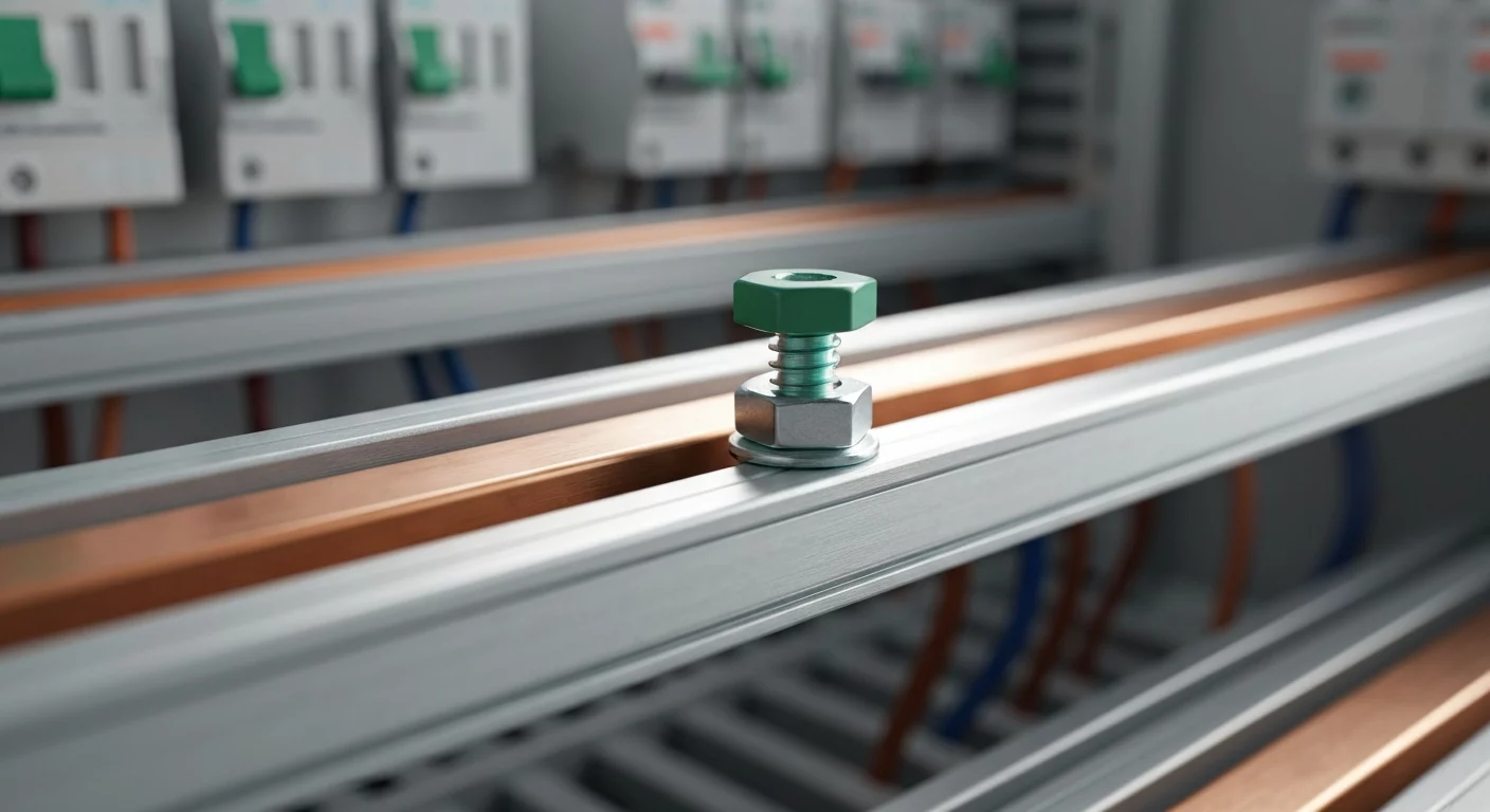
The NEC specifies the main bonding jumper is normally an unspliced connection in the service equipment enclosure, typically at the main breaker panel that serves as the service disconnect. In most installations the bond is installed at the service disconnecting means; however, the Code also includes permitted exceptions (for example, listed multi-enclosure service equipment, certain multisection switchboards or switchgear arrangements, and specified configurations for separately derived systems and supply-side bonding). The general reason this one-point bonding is required is to prevent objectionable current (neutral current on grounding conductors) from flowing on non-current-carrying metal parts during normal operation. Where an installation requires a different arrangement, the NEC lists the specific permitted options and required labeling or bonding practices so electricians must refer to Article 250 for the complete rules and exceptions. Manufacturers typically provide a green bonding screw or a bonding strap with service-rated panels to facilitate this connection, and it is the installer’s responsibility to ensure it is correctly installed at the service and left out of any subpanels unless a permitted arrangement exists.
Main Bonding Jumper vs. System and Supply-Side Bonding Jumpers
A common point of confusion for electricians undergoing electrician training is distinguishing between the main bonding jumper, system bonding jumper, and supply-side bonding jumper. While they serve similar functions, their applications are distinctly different.
- Main Bonding Jumper (MBJ): As discussed, this is typically used at the service entrance to connect the grounded conductor to the EGC system at the service equipment. It is usually unspliced and sized per the NEC bonding tables.
- System Bonding Jumper (SBJ): This jumper is used for a separately derived system, such as a generator or a transformer. It performs the same function as the MBJ—connecting the system’s grounded conductor to the equipment grounding conductors—but it does so at the source of the separately derived system, not at the building’s main service. This establishes the grounded conductor connection for that derived source.
- Supply-Side Bonding Jumper (SSBJ): This conductor ensures electrical conductivity between metallic parts and enclosures on the supply side of the service disconnect, such as ensuring metallic raceways or bus enclosures that carry the service entrance conductors are effectively bonded and connected to the grounding electrode conductor where permitted.
Understanding these distinctions is critical for code compliance. For additional context, see our comparison of the system bonding jumper vs. the supply-side bonding jumper.
How to Correctly Size Your Main Bonding Jumper
Properly sizing conductors, especially the main bonding jumper, is essential for safety. The jumper must be large enough to conduct available fault current long enough for the overcurrent device to operate without being destroyed prematurely. The sizing process follows the NEC bonding tables and guidance:
- Determine the Size of the Largest Ungrounded Conductor: Identify the size of the largest ungrounded service-entrance conductor(s) supplying the equipment. If using parallel conductors, the equivalent total circular mil area for the largest phase is the basis for sizing.
- Reference NEC Bonding Tables: Use the NEC bonding table that applies to your installation (commonly referenced as the table used for main bonding jumper sizing in Article 250). Locate the row for the largest ungrounded conductor size and read across for the minimum MBJ size for copper or aluminum.
- Apply Additional Rules for Very Large Conductors: For very large services where the ungrounded conductors exceed the table limits (for example, extremely large kcmil sizes), the Code includes an alternate rule that requires the MBJ cross-sectional area be at least a percentage of the ungrounded conductor area (see the bonding table notes for the 12.5% rule for very large conductors).
- Confirm Unspliced and Material Requirements: The NEC requires the main bonding jumper to be unspliced and lists acceptable materials and forms for the jumper (wire, bus, screw, or similar), typically copper or other corrosion-resistant materials suitable for the environment.
This sizing is different from sizing a grounding electrode conductor (GEC), which the Code covers separately; for guidance on that comparison, you may find how to size a GEC using NEC Table 250.66 helpful.
The Goal: Ensuring an Effective Ground-Fault Current Path
The ultimate goal of the main bonding jumper, and indeed the entire grounding and bonding system, is to create an effective ground-fault current path. The NEC defines this as an intentionally constructed, permanent, and low-impedance conductive path designed to carry current from the point of a ground fault back to the electrical supply source. This path must be able to safely conduct the large current available during a fault so that the overcurrent protective device will operate. The main bonding jumper is the lynchpin of this system: it connects normally non-current-carrying metallic parts (via the EGC) to the grounded service conductor, which provides a direct path back to the transformer/source. This completes the circuit, ensuring a fault is cleared quickly, protecting personnel from shock and equipment from severe damage.
Properly installing and sizing the main bonding jumper is not just about following rules; it’s about safeguarding lives. If you want to increase your practical knowledge, explore our NEC Article 250 training and our library of online electrical courses to master these critical safety concepts.
Related Resources
Frequently Asked Questions (FAQ)
What is the primary purpose of the main bonding jumper in a breaker panel?
The primary purpose of the main bonding jumper is to connect the equipment grounding conductor (EGC) bus and the service enclosure to the grounded (neutral) conductor in the main service equipment. This creates an effective ground-fault current path, which is a low-impedance route for fault current to return to the source, ensuring the overcurrent device (breaker or fuse) trips quickly.
Can I install a main bonding jumper in a subpanel?
No. As a general NEC rule, the main bonding jumper is intended at the service equipment; installing a neutral-to-ground bond in a subpanel (i.e., bonding the neutral bus to the enclosure on the load side) creates parallel neutral/ground paths and is not permitted except where the Code specifically allows an arrangement. Keep the neutral and equipment grounding paths separate on the load side.
How is a main bonding jumper different from a system bonding jumper?
A main bonding jumper is used at the service entrance for a grounded distribution system. A system bonding jumper serves the same purpose for a separately derived system (generator or transformer) by connecting that derived system’s grounded conductor to the system equipment grounding conductor at the derived source.
What NEC table do I use for sizing a main bonding jumper?
Use the NEC bonding tables in Article 250 (commonly referenced as Table 250.102(C)(1) in many presentations) to determine MBJ size based on the largest ungrounded service-entrance conductor. Refer to Article 250 for the full table and its notes.
Continuing Education by State
Select your state to view board-approved continuing education courses and requirements:
Disclaimer: The information provided in this educational content has been prepared with care to reflect current regulatory requirements for continuing education. However, licensing rules and regulations can vary by state and are subject to change. While we strive for accuracy, ExpertCE cannot guarantee that all details are complete or up to date at the time of reading. For the most current and authoritative information, always refer directly to your state’s official licensing board or regulatory agency.
NEC®, NFPA 70E®, NFPA 70®, and National Electrical Code® are registered trademarks of the National Fire Protection Association® (NFPA®)
You may also like

Colorado Electrical Licensing Requirements and Reciprocity Guide

Standby Generators in DE: Navigating Coastal Storm Regulations
