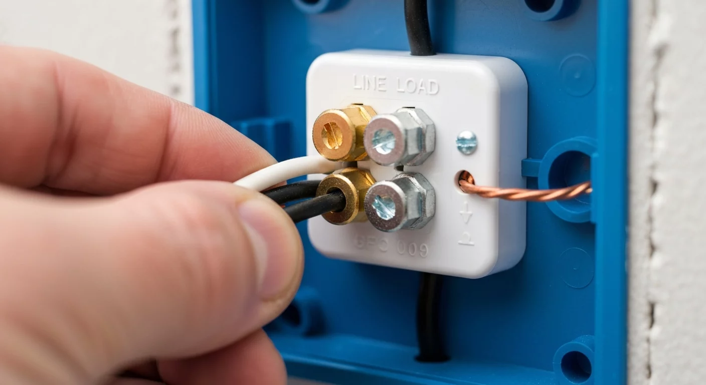
Identifying Line, Load, and Ground on a Standard Receptacle
Receptacle Line vs Load: A Professional Guide to Identification and Wiring
Correctly identifying the difference between receptacle line vs load is a fundamental skill for any journeyman electrician or residential electrician. The “line” side of a receptacle is the source of incoming power from the electrical panel, while the “load” side is the outgoing power that feeds subsequent devices in the same branch circuit. Misunderstanding this distinction, especially with GFCI outlet wiring, is a common and dangerous mistake. Properly wired, a GFCI receptacle uses its line and load terminals to protect all downstream receptacles. Incorrect wiring can render this protection useless, creating a serious safety hazard and failing electrical inspections. The core receptacle meaning in this context involves understanding the flow of electricity and ensuring safety devices function as intended by the NEC code book.
Understanding the Fundamentals: Line, Load, and Ground Explained
In any electrical circuit, power flows in a specific direction from the source to the devices it energizes. For electricians working with receptacles, understanding the terminology for this flow—line, load, and ground—is essential for safety, functionality, and code compliance. These terms define the role of each wire connected to a device.
Line: The Incoming Power Source
The “line” wire (or set of wires) is the source of power. It is the conductor that brings electrical current from the electrical service panel or an upstream vs downstream device. Think of it as the “in” connection. When dealing with a typical 120‑volt circuit, the line side consists of:
- A hot wire: Usually black or red, this wire carries the voltage. Hot wire identification is the first step in determining the line connection.
- A neutral wire: Almost always white, this wire completes the circuit by providing a return path for the current.
On a standard duplex receptacle that is the first device in a circuit, only line wires will be present. For devices in the middle of a run, the line wires are the ones carrying power from the panel.
Load: The Outgoing Power Path
The “load” wire (or set of wires) carries power away from the receptacle to other devices further down the circuit. These are often called downstream receptacles. Think of it as the “out” connection. If you disconnect a receptacle and find two sets of wires, one set is the line (power in) and the other is the load (power out). The load side also consists of a hot and a neutral wire that continue the circuit direction to the next outlet, switch, or fixture.
While standard receptacles have common terminal screws that allow for this “feed‑through” wiring, the distinction becomes critically important on a GFCI receptacle, where specific LINE and LOAD terminals must be used correctly. One important note about standard duplex devices: their hot terminals are usually bridged by a factory tab so swapping wires on the binding screws does not affect the device — but if that tab has been removed to create a split (multiwire) receptacle, then the two halves are separate circuits and the line/load assignment does matter.
Equipment Ground: The Safety Path
The equipment ground wire, typically a bare copper or green‑insulated wire, is a safety feature. It provides a path for fault current to travel to the ground in the event of a short circuit, tripping the circuit breaker and preventing electric shock. It connects to the green hexagonal screw on a receptacle and should be continuous throughout the entire branch circuit.
Why Differentiating Receptacle Line vs Load is Critical for NEC Compliance
Mistaking line and load wires can range from a minor inconvenience to a life‑threatening error. The most significant implications arise during GFCI wiring. A Ground Fault Circuit Interrupter is designed to protect against electrocution by monitoring the current balance between the hot and neutral conductors. If it detects an imbalance (meaning current is leaking to ground), it trips in milliseconds.
The 2023 NEC code book has expanded requirements for GFCI and AFCI protection in residential and commercial locations, making this skill more critical than ever. When a GFCI receptacle is wired correctly, with the incoming power connected to the LINE terminals and the outgoing power connected to the LOAD terminals, it provides protection to both itself and all other standard receptacles wired downstream from it.
If the line and load connections are reversed or miswired, the GFCI’s internal circuitry will not be able to protect the downstream portion of the circuit even if the device itself powers up. Because of that, correct LINE/LOAD wiring — or an intentional pigtail strategy when appropriate — is critical for safety and inspection compliance. For an in‑depth look at how recent code changes affect termination types and ratings, consult your current NEC references and manufacturer instructions for the devices you use.
A Step‑by‑Step Guide to Identifying Line and Load Wires
When you encounter a junction box with multiple cables, you must determine which set of wires is the line. This requires a safe, systematic process using the right tools.
- Safety First: De‑energize the Circuit. Before touching any wires, locate the correct breaker in the electrical service panel and turn it off. Use lockout/tagout if available and appropriate for the site.
- Verify Power is Off (Initial Check). Use a non‑contact voltage tester to get a quick presence check, then confirm with a properly rated multimeter or voltage tester that the circuit is de‑energized. Non‑contact testers are useful for a preliminary check but should not be the only tool you rely on.
- Disconnect and Separate Wires. Carefully unscrew the receptacle from the box and disconnect all wires from its terminal screws. Gently separate the sets of wires within the box so that no copper ends are touching each other or the metal box.
- Label and Test Without Unnecessary Risk. The safest workflow is to keep the circuit de‑energized and use a meter to trace continuity, or use a meter at the panel to identify which breaker/phase feeds which cable. If you must re‑energize the circuit to positively identify the live set, follow site lockout/tagout, wear appropriate PPE, use an approved multimeter to identify the hot conductor, and keep all hands and tools clear of exposed conductors while re‑energized.
- Identify the Line Wires. The wire that shows voltage on a reliable meter is the LINE hot; the neutral bundled with it is the LINE neutral. The other set that remains non‑energized when the circuit is live is the LOAD set that continues the circuit downstream.
- De‑energize, Verify, and Label. Once identified, de‑energize again, confirm with test instruments that power is off, and label the LINE and LOAD conductors with tape or a marker. Now you can install the new receptacle correctly or proceed with the required wiring change. For a full walkthrough, refer to our complete electrical receptacle installation guide.
Common Wiring Scenarios and Best Practices
Understanding the theory of line vs. load is one thing; applying it in the field is another. Here are common scenarios and a best practice that improves circuit reliability.
Pigtail Wiring: A More Robust Connection
Instead of using the receptacle’s terminals to feed power through to the next outlet, many professional electricians prefer pigtail wiring. This involves connecting the incoming line hot, the outgoing load hot, and a short “pigtail” wire together with a wire nut. The pigtail is then connected to the receptacle’s terminal screw.
This method offers superior reliability. If a receptacle fails or a connection on its screw terminal becomes loose, only that single outlet loses power. The rest of the downstream receptacles remain operational because their connection is independent of the device. Pigtailing is the standard and recommended method for wiring a basic duplex receptacle when multiple cables are in the box.
GFCI Wiring: The Most Common Line vs. Load Application
As discussed, GFCI wiring is where the receptacle line vs load distinction is mandatory. The terminals on a GFCI are clearly marked:
- LINE Terminals: Connect the incoming power source here. This powers the GFCI device itself.
- LOAD Terminals: Connect the outgoing power wires here. Anything connected to these terminals will be protected by the GFCI if wired correctly.
If you have downstream outlets that do require GFCI protection, connect them to the GFCI’s LOAD terminals. If the downstream outlets do not need GFCI protection, you can pigtail the conductors to feed them without placing them on the GFCI’s LOAD side — but remember that in that configuration the downstream outlets will not be protected by that device and would need their own GFCI if code requires protection there. To ensure you’re performing this critical task correctly, it helps to learn the specifics of wiring a GFCI outlet using the line and load terminals.
Key Considerations for Receptacle Wiring
- Always remember: Line is the source of incoming power; Load is the path for outgoing power.
- Reversing line and load on a GFCI receptacle is a serious safety error that disables its primary function of protecting downstream receptacles.
- Always verify circuits with a reliable meter and use lockout/tagout and PPE — non‑contact testers are good for a quick check but not a substitute for a meter.
- For enhanced circuit integrity and easier troubleshooting, use the pigtail wiring method for all middle‑of‑run receptacles.
- Always consult the current NEC and manufacturer instructions for specific requirements regarding GFCI and AFCI protection in different areas of a building; code requirements are updated periodically and the devices you install must be used as listed and marked.
Primary Sources
- National Fire Protection Association (NFPA) for information on the National Electrical Code (NEC).
Frequently Asked Questions (FAQ)
What happens if you mix up line and load on a receptacle?
On a standard duplex receptacle, swapping the two feed‑through connections usually does not change the behavior because factory‑bridged terminals (the tab) connect the pair — but remember the important exception: if the hot‑side tab is removed to create a split (multiwire) receptacle, then the two halves are separate circuits and the line/load assignment is meaningful. On a GFCI receptacle, reversing line and load will disable the device’s downstream protection even if the face of the device appears powered.
Can I connect both sets of wires to the LINE terminals of a GFCI receptacle?
Yes, by using the pigtail wiring method. You would tie the incoming and outgoing conductors together and attach a short pigtail to the device LINE terminal. That keeps the downstream conductors fed but does not place them under that GFCI’s protection. If downstream protection is required by code, the downstream conductors must be on the GFCI LOAD terminals or protected by their own GFCI.
How does pigtail wiring relate to receptacle line vs load?
Pigtail wiring effectively combines the incoming (line) and outgoing (load) conductors before they connect to the receptacle. This makes the receptacle itself an “end‑of‑run” device in the wiring scheme even if it sits mid‑run physically. It simplifies the connection to the device terminals while ensuring a solid pass‑through connection for the rest of the circuit.
Do all duplex receptacles have line and load terminals?
No. Only devices that provide some form of circuit protection or that explicitly identify separate terminals — like a GFCI receptacle or an AFCI receptacle — have distinct LINE and LOAD terminals. A standard duplex receptacle typically has two pairs of terminal screws on each side that are factory‑bridged; unless that bridge is intentionally removed (for a split receptacle), the device does not distinguish line versus load.
Continuing Education by State
Select your state to view board-approved continuing education courses and requirements:
Disclaimer: The information provided in this educational content has been prepared with care to reflect current regulatory requirements for continuing education. However, licensing rules and regulations can vary by state and are subject to change. While we strive for accuracy, ExpertCE cannot guarantee that all details are complete or up to date at the time of reading. For the most current and authoritative information, always refer directly to your state’s official licensing board or regulatory agency.
NEC®, NFPA 70E®, NFPA 70®, and National Electrical Code® are registered trademarks of the National Fire Protection Association® (NFPA®)
You may also like

Colorado Electrical Licensing Requirements and Reciprocity Guide

Standby Generators in DE: Navigating Coastal Storm Regulations
