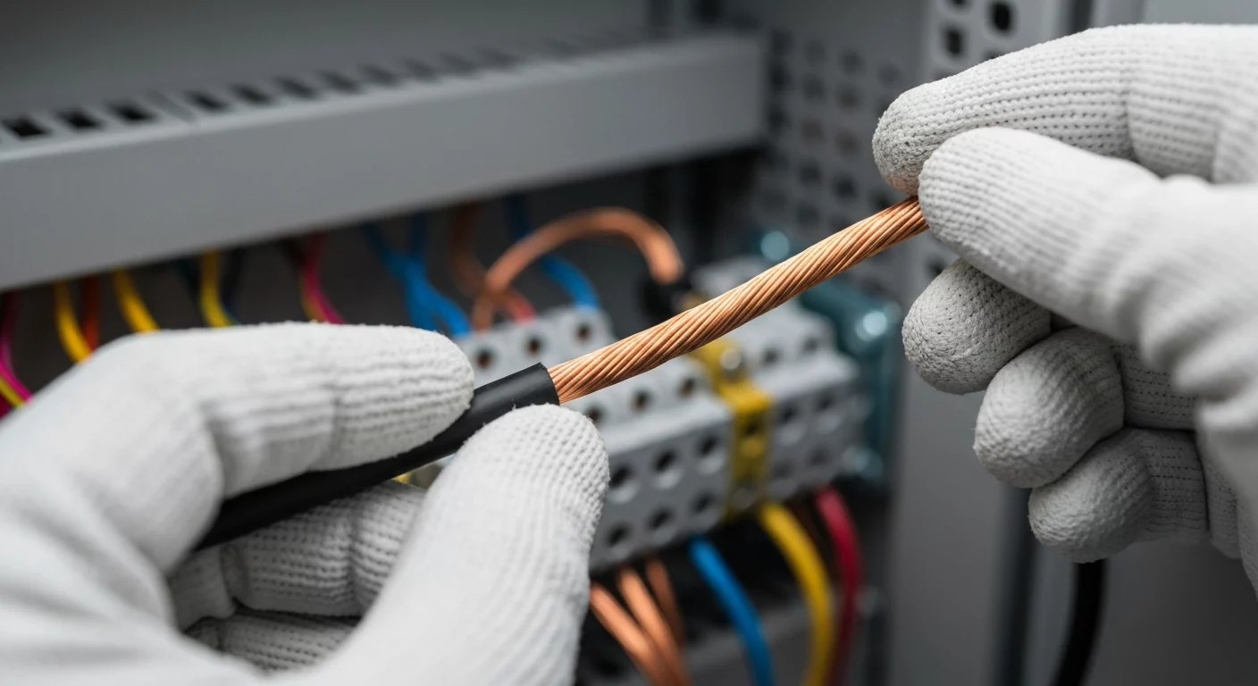
How to Size Wire for a 100 Amp Subpanel: A Step-by-Step Guide
Answering Your Core Question: What Size Wire for 100 Amp Service?
For a typical 100 amp subpanel feeder, the standard answer for what size wire for 100 amp service is #3 AWG copper or #1 AWG aluminum. This is based on the 75°C column of the primary wire ampacity chart, NEC Table 310.16. However, this is not a one-size-fits-all answer. The correct 100 amp wire size depends on crucial factors including the conductor’s temperature rating (e.g., THHN), ambient temperature, and the number of current-carrying conductors in a raceway. A proper wire size computation is mandatory for a safe and code-compliant installation. You must always consult the National Electrical Code (NEC), specifically NEC 310.16, and apply all necessary adjustment and correction factors to determine the final 100 amp sub panel wire size. Incorrect sizing can lead to overheating, equipment damage, and significant safety hazards.
Understanding the Fundamentals of Wire Sizing
Properly sizing a conductor is one of the most fundamental skills for a licensed electrician. It’s not just about making a connection; it’s about ensuring the safety and longevity of the entire electrical system. The core principle behind this is ampacity, which is the maximum current, in amperes, that a conductor can carry continuously under the conditions of use without exceeding its temperature rating. Exceeding this wire ampacity can melt insulation and create a fire hazard. The material of the wire, either copper or aluminum, is a primary factor. While many prefer copper wire for 100 amp service due to its higher conductivity, using aluminum wire for 100 amp subpanel installations is a common, cost-effective, and safe alternative when properly installed with appropriately rated terminals.
The Core of Conductor Sizing: NEC Table 310.16
The definitive guide for determining conductor size is the National Electrical Code (NEC). Specifically, the ampacity table you will use most often is Table 310.16, “Ampacities of Insulated Conductors.” This nec ampacity chart is the foundation for nearly all wire sizing. When viewing this nec wire ampacity chart, you’ll see columns for different insulation temperature ratings, primarily 60°C, 75°C, and 90°C. Per NEC 110.14(C)(1), terminations are typically limited to the 75°C column unless the equipment and terminals are specifically marked for 90°C. This nec wire size chart provides the baseline ampacity of cable table from which all other calculations begin. Whether determining the 50 amp wire size, 60 amp wire size, 40 amp wire size, or 30 amp wire size, this nec wiring size chart is your primary reference.
Step-by-Step Guide to Sizing a 100 Amp Subpanel Feeder
Determining the correct wire size for 100 amp sub panel installations requires a systematic, code-based approach. Following these steps ensures a compliant and safe installation.
- Perform the Subpanel Load Calculation: Before selecting a wire, you must calculate the anticipated load the subpanel will serve. This involves a detailed subpanel load calculation as outlined in NEC Article 220. It’s a mistake to assume a 100A subpanel will always carry a 100A load. For an in-depth review of these critical calculations, especially with recent code updates, explore our expert guide on how the 2023 NEC changes dwelling unit load calculations.
- Select Conductor Material (Copper vs. Aluminum): Based on your load calculation and project budget, choose your conductor material. Consulting the electrical wire size chart, you’ll see that for a 100A load (at 75°C), you’d look at #3 AWG copper or #1 AWG aluminum. It’s essential to understand the ampacity of different sizes, like the #2 aluminum ampacity or 3/0 copper wire ampacity, for different applications. For larger services, such as a 200 amp service wire size, you might consider 2/0 aluminum wire or even 4/0 aluminum wire. For a 100A feeder, a 1/0 al wire is a common choice.
- Consult the Ampacity Chart NEC (Table 310.16): With your load and material determined, locate the ampacity in the 75°C column of the nec ampacity table that is equal to or greater than your load. This gives you the initial 100 amp service wire gauge before any adjustments.
- Apply Ampacity Adjustment and Correction Factors: This is a critical step. You must apply ampacity adjustment factors if you have more than three current-carrying conductors in a single raceway or cable (Table 310.15(C)(1)). You must also apply conductor temperature correction factors if the ambient temperature is not 30°C (86°F) (Table 310.15(B)(1)). These factors can significantly impact the required cable gauge awg. Poor planning for conduit fill for 100 amp feeder can force you to use a much larger, more expensive wire. The high temperature rating of conductors like THHN wire ampacity (90°C) can be used for these derating calculations, provided the final ampacity does not exceed the 75°C rating of the terminals.
- Verify with a Voltage Drop Calculation: For long feeder runs, you must perform a voltage drop calculation 100 amp. The NEC recommends a maximum of 3% voltage drop for a feeder. If your calculation shows a drop greater than 3%, you must increase your conductor size, regardless of what the ampacity tables say. A good wire length calculator can assist with this, but you must understand the underlying formula.
- Determine the Equipment Grounding Conductor (EGC) Size: Finally, size your ground wire. The grounding conductor size for 100 amp is determined by NEC Table 250.122, based on the rating of the overcurrent protective device (the 100A breaker). A quick look at a ground wire size chart or the nec ground wire size chart shows that for a 100A OCPD, you need a #8 AWG copper or #6 AWG aluminum EGC. Note that if the ungrounded conductors are increased in size (e.g., for voltage drop), the EGC may also need to be proportionally increased per NEC 250.122(B). Always reference the official equipment grounding conductor chart.
Ensure your service and feeder calculations are accurate and code-compliant. A mistake in wire sizing is not just a code violation—it’s a serious safety risk.
Branch Circuit Loads: A Key Part of Your Subpanel Plan
When planning your subpanel, it’s crucial to understand the branch circuits it will supply. This knowledge is essential for your initial load calculation. Common questions arise, such as how many outlets on a 20 amp circuit? The NEC doesn’t set a specific limit for dwelling units, but a common rule of thumb is 8-10 receptacles. For commercial work, the load is calculated at 180VA per yoke, meaning you can have 13 receptacles on a 20A, 120V circuit. The same logic applies to how many receptacles on a 20 amp circuit or how many outlets on a 15 amp circuit. It’s also important to understand the load of specific equipment. For example, knowing the average dryer wattage helps in calculating demand factors. You might even consider specialized needs like how many computer on one breaker to avoid nuisance tripping. Understanding that placing a 20 amp outlet on a 15 amp circuit is a code violation (per 210.21(B)(3)) is also part of this holistic planning. A 15A circuit can have a maximum of a 15A receptacle, while a 20A circuit can have either 15A or 20A receptacles. Answering how many watts on a 15 amp circuit is simple: 1,800 watts (15A x 120V), with continuous load limited to 80% of that, or 1,440 watts.
Important Sizing Considerations and Quick Reference
Knowing how to know what gauge wire to use comes with experience and repeated use of the NEC. Below are key points and common sizes to keep in mind, derived from the wire amperage chart, which is also called a wire amp chart or nec wire amperage chart.
- SER Cable Sizing: For 100 amp SER cable sizing feeding a subpanel, use Table 310.16. Do not confuse this with NEC Table 310.12, which allows an 83% reduction for the *main service* conductors to a dwelling, not subpanel feeders.
- Common Breaker Sizes: A 100 amp breaker wire size is our focus here, but for a 60 amp breaker wire size, you’d typically use #6 AWG copper. For what size wire for 50 amp breaker, it’s usually #8 AWG copper. Always verify with the nec code wire size chart.
- Quick Ampacity Reference: The amp rating for 8 gauge wire is typically 40A or 50A depending on material and temperature rating. The 8 awg wire amps can be found on any electrical wire size table. The 8 awg ampacity (specifically 8 thhn ampacity or 8awg wire ampacity) is 55A in the 90°C column, but limited to 50A by the 75°C termination rule. Similarly, the 4 awg wire ampacity is 85A (CU, 75°C) and the 2 awg ampacity is 115A (CU, 75°C). The 14 gauge wire amps rating is 15A.
- Special Cases: For very large loads, such as a 400 amp wire size, you would typically use parallel conductor runs. A single 4/0 aluminum electrical wire is not sufficient for a 400A load; its 4/0 aluminum wire ampacity is only 180A (at 75°C). You may need parallel 3/0 copper wire ampacity runs or larger.
Primary Sources
For the most accurate and up-to-date information, always refer to the official source for electrical code. The NEC is published by the National Fire Protection Association (NFPA).
Frequently Asked Questions (FAQ)
- What size wire for 100 amp service is required for a subpanel feeder?
- The standard 100 amp subpanel feeder size is #3 AWG copper or #1 AWG aluminum wire, based on the 75°C column of NEC Table 310.16. This is the starting point before applying mandatory adjustments for ambient temperature and conduit fill, which may require a larger wire size.
- Can I use 4/0 aluminum wire for a 200 amp service, and what about for a 100 amp subpanel?
- Yes, in many cases. While 4/0 aluminum wire has an ampacity of 180A at 75°C (per NEC Table 310.16), NEC 310.12(A) allows it to be used for a 200 amp service wire size for a dwelling unit. This is because the code permits these specific service conductors to be sized at 83% of the service rating (200A x 0.83 = 166A, so the 180A wire is sufficient). However, for a 100 amp subpanel, using 4/0 aluminum wire would be extreme overkill and not cost-effective. The correct size of wire for 60 amp, for example, is much smaller.
- How do I read a wire ampacity chart or ampacity table from the NEC?
- To read a wire ampacity chart like the nec amp chart (Table 310.16), first identify the material (copper or aluminum). Then, find the wire gauge (AWG or kcmil) in the first column. Move across that row to the column corresponding to the conductor’s insulation rating, but remember that you are typically limited to the 75°C column for terminations. This value is the conductor’s baseline ampacity before any derating. Whether you need the 50 amp wire, wire size for 60 amp, or are looking at a general nec ampacity chart, the process is the same.
Continuing Education by State
Select your state to view board-approved continuing education courses and requirements:
Disclaimer: The information provided in this educational content has been prepared with care to reflect current regulatory requirements for continuing education. However, licensing rules and regulations can vary by state and are subject to change. While we strive for accuracy, ExpertCE cannot guarantee that all details are complete or up to date at the time of reading. For the most current and authoritative information, always refer directly to your state’s official licensing board or regulatory agency.


