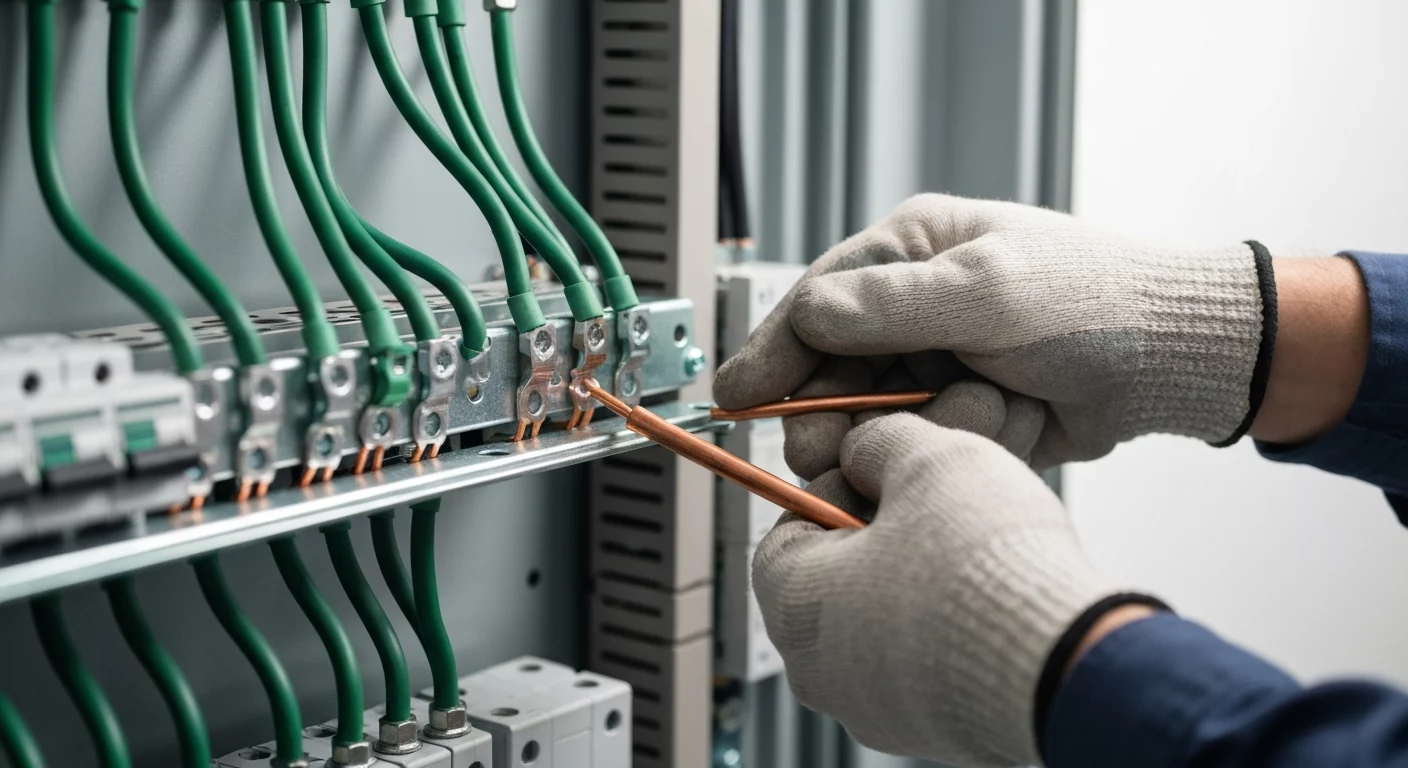
Grounding vs. Bonding: A Guide to NEC Article 250
For licensed electricians, mastering the concepts of grounding and bonding is non-negotiable for ensuring electrical safety and code compliance. While often used interchangeably in casual conversation, these two terms represent distinct, yet related, functions critical to a properly installed electrical system. Grounding is the act of connecting an electrical system to the earth itself, primarily for protection from lightning and voltage stabilization. Bonding, conversely, is the practice of connecting all metallic parts of an electrical system that are not meant to carry current together to create a low-impedance path. This path, known as an effective ground-fault current path, is essential for the overcurrent protection device to operate and for clearing a ground fault. A thorough understanding of the complete grounding electrode system and the specific NEC Article 250 requirements is fundamental to any professional installation.
The Core Distinction: Grounding vs. Bonding
At the heart of NEC Article 250 lies a fundamental distinction. Think of it this way: grounding connects us to the planet, while bonding connects everything to itself. The common confusion between ground vs neutral wire or neutral vs earth stems from not separating these two purposes.
- Grounding: Its primary purpose is to connect the electrical system’s circuits to the earth or to a conductive body that serves in place of the earth. This connection helps stabilize voltage during normal operation and provides a path for high-voltage events like lightning strikes or utility line surges, protecting the system from external threats.
- Bonding: Its purpose is safety for people and property from electrical shock. It ensures that all non-current-carrying metallic components (conduit, enclosures, frames) are at the same electrical potential. If a fault occurs where an energized conductor touches a bonded part, bonding provides a low-impedance path for the fault current to flow back to the source, tripping the breaker or blowing the fuse.
Understanding Grounding: The Earth Connection
The entire grounding system begins with its connection to the physical earth. This is achieved through a carefully designed and installed grounding electrode system.
The Grounding Electrode System
The earth itself is the ultimate reference point for the electrical system. A grounding electrode is the component in direct contact with the earth. While several types exist (concrete-encased electrodes, plates, etc.), the most common is the grounding rod. NEC 250.52 lists acceptable electrodes, and often, multiple types like a water pipe and grounding rods must be used together to form the complete system.
The Grounding Electrode Conductor (GEC)
The wire that connects the grounded service conductor to the grounding electrode is the grounding electrode conductor. The proper earthing size for this conductor is determined by NEC Table 250.66, based on the size of the ungrounded service-entrance conductors. This conductor is not designed to carry fault current from an equipment fault; its job is to handle lightning and stabilize voltage.
Step-by-Step Electrical Ground Rod Installation
Proper ground rod installation is critical for the system’s effectiveness. When an electrical ground rod is required, follow these steps based on NEC 250.53:
- Select the Rod: The standard rod must be at least 8 feet in length and listed for the purpose.
- Determine Location: The question of where do you install grounding rod is answered by NEC 250.53(A). It must be driven to a depth of 8 feet. If rock bottom is hit, it can be driven at a 45-degree angle or, as a last resort, buried in a trench at least 30 inches deep.
- Drive the Rod: Drive the rod vertically until 8 feet of its length is in contact with the soil. The top of the rod can be at or below grade level.
- Make the Connection: Use a listed and irreversible connector (like an acorn clamp) to attach the grounding electrode conductor to the rod. This connection must be secure and protected from physical damage. This is a crucial step in a compliant electrical ground rod installation.
Bonding: What Is It? Creating an Effective Ground-Fault Current Path
If grounding is about connecting to the earth, bonding is about creating a safety net. The main goal is to ensure an effective ground-fault current path. This path is an intentionally created, low-impedance conductive path designed to carry current from the point of a ground fault on a wiring system to the electrical supply source. This ensures the fault current is high enough to trip the overcurrent device, a process known as clearing a ground fault.
Key Bonding Components
- Main Bonding Jumper (MBJ): The most critical link. The main bonding jumper creates the connection between the grounded conductor (neutral) and the equipment grounding conductor at the service equipment. This is the only place in a standard system where the neutral ground connection is intentionally made.
- System Bonding Jumper: Used for separately derived systems (like a transformer or generator) to connect the system’s grounded conductor to the equipment grounding conductor for that system.
- Supply-Side Bonding Jumper: A conductor on the supply side of a service that ensures the required conductivity for the ground-fault current path.
- Bonding Jumper / Bonding Bushing: A general bonding jumper connects two or more parts of the equipment grounding conductor system. A bonding bushing (or a grounding bushing) is used on conduits entering enclosures to ensure they are properly bonded to the system. Proper service equipment bonding is a core safety requirement.
The Role of Conductors: EGCs and Grounded Conductors
Two key wires are involved in the path: the equipment grounding conductor (EGC) and the grounded conductor.
The Equipment Grounding Conductor (EGC)
This is the path from the faulted equipment back to the panel. The EGC can be a dedicated grounding wire or grounding cable, or it can be the metallic raceway itself (like EMT). Its job is to carry fault current, so it must be properly sized and installed. Sizing is critical, and electricians must understand how equipment grounding conductor sizing and splicing rules have changed in the 2023 NEC to remain compliant.
The Grounded Conductor (Neutral)
The grounded conductor, typically the neutral, is the return path for the fault current from the panel back to the utility transformer. The connection made by the main bonding jumper forces the fault current onto this path, completing the circuit and tripping the breaker.
Advanced Concepts and Special Applications
The principles of grounding and bonding extend into more complex scenarios.
- Separately Derived Systems: When dealing with generators or transformers, a new system is “derived.” You must establish a system bonding jumper at the first disconnect to create the necessary neutral-ground bond for that system. Troubleshooting issues like a specific solar charge inverter 20v neutral to ground voltage reading often comes down to correctly identifying and bonding these systems.
- Intersystem Bonding: The intersystem bonding termination is the required connection point for other systems entering the building, like telephone and CATV. This prevents potential differences between systems, and proper intersystem bonding between these systems is crucial.
- Objectionable Current: NEC 250.6 addresses objectionable current flowing on the EGCs during normal operation. This is often caused by improper neutral-to-ground connections downstream of the main service disconnect.
- Special Locations: Areas like swimming pools, agricultural buildings, and healthcare facilities have unique requirements, often involving the creation of an equipotential plane to minimize voltage differences. For example, the NEC has specific rules detailing how the 2023 NEC simplifies healthcare facility panelboard bonding. Similarly, hazardous locations have stringent rules, and it’s important to know how grounding and bonding requirements in Class I, Division 1 and 2 locations are different.
- Utility Systems: You may encounter terms like single wire earth return (SWER), which is a cost-saving method for delivering power in rural areas. This is a utility-side practice and is not permitted by the NEC for premise wiring systems.
Key Takeaways from the 2023 NEC 250 Changes
The NEC is constantly evolving, and the 2023 NEC 250 changes introduced several important updates that professionals must be aware of. Staying current is key to safe and compliant installations.
- GEC Splices (250.64(C)): The list of approved methods for splicing the grounding electrode conductor has been expanded.
- Bonding of Fences and Gates (250.194): New language clarifies when fences and gates near outdoor electrical equipment need to be bonded to prevent shock hazards.
- Separately Derived Systems (250.30): The rules for the location of the system bonding jumper have been refined to provide clearer guidance for installers.
- High-Impedance Grounded Systems: There are updated requirements for specifying and installing these specialized systems often found in industrial facilities.
The complexity and critical nature of these rules underscore the need for continuous education. Master NEC Article 250, one of the most important articles in the code, with expert-led online courses designed for licensed professionals.
Primary Sources for This Article
The information presented is based on the standards and requirements set forth in the NFPA 70, National Electrical Code (NEC), primarily Article 250. For the most current and detailed requirements, always refer to the latest edition of the code adopted by your local jurisdiction.
Frequently Asked Questions (FAQs) about Grounding and Bonding
What is the main difference between a ground vs neutral wire?
The main difference lies in their intended function. The neutral wire (the grounded conductor) is a current-carrying conductor designed to complete the circuit and carry current back to the source during normal operation. The ground wire (the equipment grounding conductor) is a non-current-carrying safety wire that only carries current during a ground-fault condition to facilitate the opening of the overcurrent device.
What is the purpose of the main bonding jumper in an electrical service?
The main bonding jumper (MBJ) provides the critical connection between the equipment grounding conductor system and the grounded (neutral) conductor at the main service disconnect. Its sole purpose is to create a low-impedance path for fault current to flow from the equipment grounding system back to the utility source via the neutral, which is essential for clearing a ground fault quickly.
Are there specific NEC Article 250 requirements for grounding rod installation?
Yes, NEC Article 250 requirements are very specific. Section 250.53 mandates that a standard rod-type electrode must have at least 8 feet of its length in direct contact with the soil. If it cannot be driven vertically for 8 feet due to rock, it can be driven at an angle not to exceed 45 degrees or buried in a trench that is at least 30 inches deep. This ensures an effective connection to the earth.
Continuing Education by State
Select your state to view board-approved continuing education courses and requirements:
Disclaimer: The information provided in this educational content has been prepared with care to reflect current regulatory requirements for continuing education. However, licensing rules and regulations can vary by state and are subject to change. While we strive for accuracy, ExpertCE cannot guarantee that all details are complete or up to date at the time of reading. For the most current and authoritative information, always refer directly to your state’s official licensing board or regulatory agency.


