DIY Generator Transfer Switch: A Pro’s Guide to Safe Installs
Article Summary: A professional guide for licensed electricians on the safe and code-compliant installation of generator transfer switches. For licensed electricians, a “DIY generator transfer switch” project is a common task, but it must adhere to strict safety standards to prevent lethal backfeed. This involves choosing between a manual transfer switch (MTS) and a generator interlock kit, performing a detailed load calculation, and understanding the nuances of NEC Article 702. Proper installation is the only way to guarantee backfeed prevention, protecting utility workers and the home’s electrical system. This guide covers critical topics including system types, neutral bonding, permit requirements, and the correct procedures for integrating portable generators into residential standby power systems.
The Professional’s “DIY”: Why Your License Matters for Generator Installs
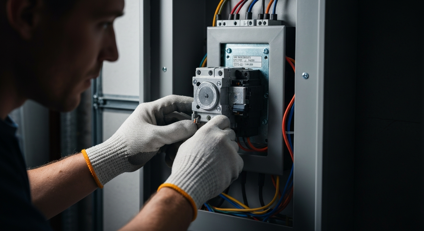
In the electrical trade, the term “DIY” takes on a different meaning. When we discuss a diy generator transfer switch installation, we aren’t referring to a homeowner project. We are talking about a job handled by a qualified, licensed electrician from start to finish. The risks associated with improperly connecting a generator to a dwelling’s electrical system are severe, ranging from destroyed appliances to electrocution and fire. The most critical danger is electrical backfeed, which can energize utility lines and kill line workers. This is why any generator interconnection work requires a deep understanding of the National Electrical Code (NEC) and local regulations. Before any work begins, the first step is always to secure an electrical permit for generator installation from the local Authority Having Jurisdiction (AHJ).
Core Safety Principle: The Absolute Need for Backfeed Prevention
The single most important function of a transfer switch or interlock kit is backfeed prevention. A transfer switch is a mechanical device that ensures a home’s electrical system cannot be connected to both the utility grid and the generator simultaneously. It creates an unbreakable “either/or” scenario. Without this safeguard, a running generator can send electricity back through the utility transformer, stepping up the voltage to deadly levels on the power lines that line workers believe are de-energized. Adhering to NEC 702.5, which mandates a method to prevent the inadvertent interconnection of primary power sources, is not just a rule—it’s a life-saving requirement.
Choosing the Right Transfer Method: MTS vs. Interlock Kit
As a professional, you have two primary, code-compliant methods for safely connecting a portable generator. The choice depends on the homeowner’s needs, budget, and the existing panel configuration.
The Manual Transfer Switch (MTS) and Critical Load Subpanel
A manual transfer switch (MTS) is often installed alongside a critical load subpanel. This setup allows you to move essential circuits—like the refrigerator, furnace blower, well pump, and a few lighting/receptacle circuits—from the main panel to the new subpanel. The MTS then allows the homeowner to switch this entire subpanel’s power source from ‘LINE’ (utility) to ‘GEN’ (generator). This is a clean, intuitive solution that isolates only the most important loads, preventing the generator from being overloaded. It provides a clear, designated path for backup power.
The Generator Interlock Kit: A Cost-Effective Alternative
A generator interlock kit is a simpler mechanical device installed directly on the main service panel. It consists of a sliding metal plate that prevents the main breaker and a designated generator back-feed breaker from being in the ‘ON’ position at the same time. To use the generator, the user must turn off the main breaker first, slide the interlock plate, and then turn on the generator breaker. While more affordable, this method energizes the entire panel, requiring the user to manually turn off non-essential circuits to avoid overloading the generator. It’s crucial to use only interlock kits that are listed and labeled for the specific panel they are being installed on.
Essential Steps for a Code-Compliant Installation
A safe installation is a methodical one. Follow these steps to ensure your work is compliant, safe, and reliable.
Step 1: Performing a Meticulous Load Calculation for Generator Sizing
Before any hardware is installed, you must perform a load calculation for generator sizing to ensure the selected generator can handle the intended loads. An undersized generator will trip its breaker or sustain damage, while an oversized one is an unnecessary expense. Follow NEC Article 220 for your calculations.
- Identify Critical Loads: Work with the homeowner to list every appliance and circuit they want to power during an outage.
- Determine Wattage: Find the running watts and starting watts (for motors) for each item. The starting wattage can be 3-5 times the running wattage.
- Calculate Total Running Watts: Sum the running wattage of all items that will operate simultaneously.
- Account for Starting Watts: Identify the single largest starting wattage from your list.
- Final Calculation: Add the total running watts to the single largest starting wattage. The described method is a simplified practical estimate for portable generator sizing, but full compliance with NEC 702.4(B) and Article 220 requires applying appropriate demand factors and load diversity considerations for the specific installation, not just summing watts.
Step 2: Installing the Portable Generator Inlet Box
The portable generator inlet box is the weatherproof connection point on the exterior of the house. It should be installed in a convenient, well-ventilated location where the generator will be operated—at least 20 feet from doors and windows to prevent carbon monoxide ingress, a critical safety guideline from sources like OSHA and the CPSC. The inlet box is then wired to the transfer switch or the designated generator breaker in the main panel. Be sure to follow all 2023 NEC rules for outdoor generator inlets, which have specific requirements for location and protection.
Step 3: Making the Connections and Correcting Improper Wiring
Wiring the transfer equipment is the most critical step. This is where you’ll connect the inlet, the panel, and potentially work near the service entrance conductors. While a line-side tap is a method used in some solar and storage applications, it is generally not the preferred method for a simple portable generator setup. During this process, it’s common to discover pre-existing issues. Part of your job is correcting improper wiring to ensure the entire system is safe, not just the new components. Before tackling complex connections, ensure your knowledge is current. Specialize in backup power systems with our advanced electrical courses.
Navigating NEC Article 702 and Key Technical Details
Compliance goes beyond just the physical installation. Understanding the technical requirements of NEC Article 702 (Optional Standby Systems) is mandatory for any professional electrician.
Separately Derived System vs. Non-Separately Derived
This is one of the most misunderstood concepts in generator installs, with definitions rooted in NEC Article 100. The key is the neutral. The debate of floating neutral vs bonded neutral generators is central here.
- A separately derived system is one where the neutral is switched at the transfer switch along with the ungrounded conductors. This configuration avoids multiple neutral-to-ground bonds and is a compliant option when using a generator with an existing neutral-ground bond (per NEC 250.30). This setup isolates the home’s electrical system entirely from the utility, including the neutral, and requires a three-pole transfer switch for single-phase 120/240V systems (to switch the two ungrounded conductors and the neutral). As per NEC 100 and 250.30, this is accurate; however, for non-separately derived systems with bonded neutral generators, note that removing the generator’s bond must align with manufacturer instructions to avoid warranty issues or safety risks, as it’s not always recommended.
- A non-separately derived system does not switch the neutral. This is used with generators that have a floating neutral, as the system remains bonded to the utility’s neutral-ground connection at the service disconnect. A two-pole transfer switch (or an interlock kit, which utilizes a two-pole breaker) is appropriate here, as only the ungrounded conductors are switched.
You must check the generator’s configuration to determine the correct transfer equipment and wiring method. For a deeper dive, review the latest NEC updates on interconnection and transfer equipment.
Considerations for a Solar Power Generator for Home Integration
The term “generator” is evolving. Homeowners may ask about integrating a solar power generator for home use, which is typically a battery storage system. These systems fall under different NEC articles (like 705 and 706) and introduce new complexities, including interaction with the grid and rapid shutdown. While they can be part of robust standby power systems, their installation requirements are distinct from those for portable, fuel-powered generators and often require more advanced transfer equipment and knowledge of updated emergency stop requirements.
Primary Sources for Electrical Code and Safety
- NFPA 70: National Electrical Code (NEC)
- International Association of Electrical Inspectors (IAEI)
- OSHA – Portable Generator Safety
- Your Local Authority Having Jurisdiction (AHJ) Building Department
Frequently Asked Questions (FAQs)
Is a diy generator transfer switch installation legal for a homeowner?
Legality varies by jurisdiction. While many local codes require licensed electricians for such work, some allow homeowners to perform it on their own residence with proper permits and inspections, per state and local regulations (e.g., as guided by the ICC or local AHJ). In all cases, this complex and dangerous work legally requires an electrical permit for generator installation and a subsequent inspection to ensure safety and code compliance.
What’s the difference between a generator interlock kit and a manual transfer switch (MTS)?
A generator interlock kit is a mechanical plate that prevents the main and generator breakers from being on simultaneously. It’s a cost-effective way to power the entire panel. A manual transfer switch (MTS) is a dedicated switch that typically powers a separate subpanel of pre-selected critical circuits, offering a more user-friendly but more involved installation.
Do I need a three-pole transfer switch for my portable generator?
You might. The need for a three-pole switch depends on the system’s design—specifically, whether you are installing it as a separately derived system. If your generator has a bonded neutral, you must prevent objectionable current by either switching the neutral (which requires a three-pole transfer switch for a 120/240V system) or by removing the generator’s bond and using a two-pole switch. The choice must comply with NEC 702 and 250, and the final configuration is always subject to AHJ approval.
Continuing Education by State
Select your state to view board-approved continuing education courses and requirements:
Disclaimer: The information provided in this educational content has been prepared with care to reflect current regulatory requirements for continuing education. However, licensing rules and regulations can vary by state and are subject to change. While we strive for accuracy, ExpertCE cannot guarantee that all details are complete or up to date at the time of reading. For the most current and authoritative information, always refer directly to your state’s official licensing board or regulatory agency.


