Intersystem Bonding Termination: How to Install per NEC 250.94
An intersystem bonding termination (IBT) is a critical component mandated by the National Electrical Code (NEC) to ensure the safe integration of different electrical systems within a building. It provides a dedicated, accessible connection point for bonding other systems—such as telephone, CATV, and satellite dishes—to the building’s main grounding electrode system. Proper installation per NEC (see Article 800 and related requirements in Article 250) prevents dangerous potential differences between the power service and communication systems, especially during lightning events or utility faults. This single-point connection for the bonding conductor for communications systems is a cornerstone of effective grounding and bonding, essential for both equipment protection and life safety. Achieving National Electrical Code compliance requires a thorough understanding of the IBT’s purpose, location, and connection methods, ensuring all metallic systems share the same ground reference potential.
The Core Principle: Bonding What Is It and Why Is It Critical?
As a professional electrician, you know that grounding and bonding are foundational safety concepts, but they are not interchangeable. Grounding connects a system to the earth, while bonding connects conductive parts together to ensure they are at the same electrical potential. This principle, known as equipotential bonding, is the primary goal of the IBT.
Without a common bonding point, different systems (power, cable TV, phone lines) can have different ground references. This creates a dangerous situation. For instance, a nearby lightning strike can induce thousands of volts on a CATV coaxial cable. If that cable is not effectively bonded to the building’s electrical service ground, that voltage will seek a path to ground through any available means—often through sensitive electronics like TVs and modems, or worse, through a person. The IBT eliminates this hazard by creating a single, safe point of connection.
It’s also vital to understand the distinction between neutral vs earth or ground vs neutral wire. At the electrical service entrance, the neutral conductor and the grounding system are connected via the main bonding jumper. This establishes the system’s ground reference. Downstream from this point, the neutral (the grounded conductor) and the ground (the equipment grounding conductor) serve different functions. The IBT ensures that external, separately derived systems are tied back to this original reference point, reinforcing the concept of service equipment bonding.
Understanding the NEC Requirement for an Intersystem Bonding Termination
The NEC requires an intersystem bonding termination to be provided for connecting intersystem bonding conductors for other systems (see Article 800 for the device and Article 250 for grounding-system rules). This is an important AHJ checkpoint: the IBT makes the connection point for CATV and satellite bonding, and other communication systems, readily available and obvious to other trades.
The IBT must be:
- Accessible.
- Located at or near the meter socket enclosure or the service equipment (or otherwise in a readily accessible location permitted by the NEC).
- Equipped with capacity for at least three intersystem bonding conductors.
- Connected to the building’s grounding electrode system.
A common mistake electricians see in the field is a cable or satellite technician driving an unapproved, isolated grounding rod for their system. This creates a separate ground reference and undermines equipotential bonding; the NEC requires these systems be tied into the building’s established grounding electrode system so that all electrodes are bonded together and a single reference is maintained.
Methods of Compliance: Installing an Intersystem Bonding Termination per the NEC (see Article 800)
NEC Article 800 (800.94) outlines the permitted methods for creating a compliant IBT. These methods ensure a robust and reliable connection point and are commonly what AHJs expect to see at the service or meter.
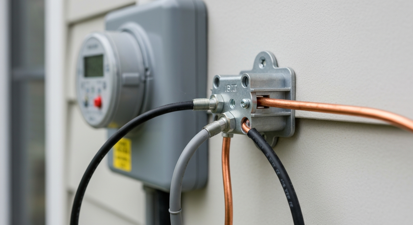
Method 1: The Intersystem Bonding Termination Device (IBTD)
The most common and recommended method is to install a listed device specifically designed for this purpose. This device—often a small listed terminal bar or listed grounding/bonding device—provides multiple lugs for connecting the bonding conductor for communications systems. The device is then connected to the building’s grounded system.
Method 2: Other Approved Means
The code also permits other connection methods, such as:
- A set of listed terminals on the outside of the service equipment or the meter socket enclosure.
- A connection to the grounding electrode conductor using a listed split-bolt or other irreversible compression-type connector.
- A connection to the metallic service raceway, service equipment enclosure, or meter base.
For more detailed information on GEC connections, it’s crucial to understand how grounding electrode conductor connections are handled in the 2023 NEC, as these rules directly impact IBT installation.
Step-by-Step Installation of an IBTD
Properly installing a grounding bridge device is straightforward but requires attention to detail.
- Identify Location: Locate the electrical service entrance equipment. The IBTD is typically mounted externally at the meter base enclosure or service equipment enclosure so other trades can access it without exposing the interior of the service equipment.
- Mount the Device: Securely mount the IBTD to the structure. Ensure it is accessible for future connections by satellite or communications technicians.
- Install the Bonding Jumper: Run a bonding jumper from the IBTD to a valid connection point. Accepted connection points include the service equipment enclosure, the metallic service raceway, the grounding electrode conductor, or the grounded service conductor at the service—consistent with NEC allowances.
- Verify Conductor Size: Proper bonding jumper sizing is critical. For the IBT connection to the building grounding electrode system, the NEC requires a conductor not smaller than 6 AWG copper (or equivalent) in many typical installations; this is to ensure it can handle significant fault or lightning currents. Note, though, that other specific bonding situations in the NEC may require different minumum sizes based on the largest ungrounded conductor or other factors.
- Confirm Connections: Ensure all connections are tight and secure. Use a listed grounding or bonding connector or the exothermic welding process for permanent bonds. Where the bonding conductor passes through an enclosure knockout, use a listed listed connector or bonding bushing to maintain a reliable bond.
Grounding Electrode System Components
The IBT is an extension of the building’s grounding electrode system. This system may include one or more electrodes such as driven rods, concrete-encased electrodes (Ufer grounds), metal underground water piping, or other electrodes permitted by the NEC. A single ground rod alone is allowed only if it meets the NEC’s supplemental-electrode rules (for example, a single rod must have a measured resistance to earth of 25 ohms or less to avoid requiring a supplemental electrode). The overall conductor sizing for the main grounding electrode conductor is determined by NEC rules (for example, based on the size of the ungrounded service-entrance conductors).
Special Cases and Advanced Concepts
The principles of single-point grounding extend beyond typical residential services and are even more critical in complex installations.
Low-Voltage and Specialized Systems
Effective low-voltage system grounding is essential for preventing noise and equipment damage. For example, a voltage reading between neutral and ground on an inverter or charger often indicates a floating ground or improper bonding. Such conditions underscore the importance of tying renewable and communications systems back to the common building reference via the IBT. For communications-specific installation considerations, see communications and CATV coaxial cable installations guidance.
In highly sensitive environments, bonding and grounding methods will be coordinated with other standards and may require engineering input; for example, healthcare and other low-voltage integration rules can impose additional requirements.
Common Misconceptions
Some systems used elsewhere in the world, such as single-wire earth return (SWER), treat earth differently. The NEC in the U.S. requires a dedicated grounding and bonding scheme and does not allow the earth to be used as a normal current-carrying conductor for distribution in typical premises wiring. The IBT enforces the NEC’s approach by tying communications and other systems into the single building reference.
Key Takeaways for AHJ Inspection Success
To ensure your installation passes inspection, focus on these key points related to AHJ inspection requirements:
- Accessibility: The IBT must be externally accessible without removing parts of the building finish.
- Location: It should be located at or adjacent to the service disconnect or meter enclosure (or as permitted by code).
- Bonding Jumper: For IBT connections to the building grounding electrode system, a bonding conductor sized per the NEC (the NEC commonly requires a 6 AWG copper minimum for typical IBT grounding connections) must be used; other NEC provisions may require larger bonding conductors depending on system size.
- Listed Device: Use a listed intersystem bonding termination device or other listed means for bonding and grounding.
- Capacity: The device must have terminals capable of accepting the required number of intersystem bonding conductors (the NEC generally specifies at least three terminals for an IBT).
Primary Sources
- NFPA 70, National Electrical Code (NEC), 2023 Edition. See Article 800 for the intersystem bonding termination device details and Article 250 for grounding-electrode-system requirements.
Frequently Asked Questions (FAQ)
What is the primary purpose of an intersystem bonding termination?
The primary purpose of an intersystem bonding termination is to provide a safe, accessible, and code-compliant single connection point for bonding other building systems (like telephone, CATV, and network) to the main electrical grounding electrode system. This practice of equipotential bonding prevents dangerous voltage differences between systems.
Can I just bond communication systems to a nearby grounding rod?
No. All bonding must be done so the communications system is tied into the building’s established grounding electrode system via a compliant IBT or other NEC-permitted means. Installing an isolated rod that is not bonded into the building grounding system creates a separate ground reference and is contrary to the NEC’s bonding objectives.
What is the difference between a ground vs neutral wire in the context of grounding and bonding?
The difference between a ground vs neutral wire is fundamental. The neutral is the grounded conductor and serves as the return path for normal circuit current; the ground wire (equipment grounding conductor) is a safety conductor normally non-current-carrying that provides a path for fault current to return to the source, enabling overcurrent devices to operate. Both are connected at the service equipment by the main bonding jumper, but they serve different functions downstream.
How does the main bonding jumper relate to the intersystem bonding termination?
The main bonding jumper at the service ties the grounded (neutral) conductor to equipment grounding conductors and the service enclosure, establishing the building’s ground reference. The IBT is an external point that ties external low-voltage systems back to that same reference so all systems share the same grounding electrode system and potential.
Continuing Education by State
Select your state to view board-approved continuing education courses and requirements:
Notes
For additional NEC detail on grounding electrode conductor connections and bonding devices: see the NEC articles referenced above (Article 800 for IBT installation details and Article 250 for grounding electrode system and bonding conductor sizing rules). For communications-specific installation guidance, you may find the previously included links helpful: how grounding electrode conductor connections are handled in the 2023 NEC, communications and CATV coaxial cable installations, and low-voltage wiring integration in specialized facilities.
Disclaimer: The information provided in this educational content has been prepared with care to reflect current regulatory requirements for continuing education. However, licensing rules and regulations can vary by state and are subject to change. While we strive for accuracy, ExpertCE cannot guarantee that all details are complete or up to date at the time of reading. For the most current and authoritative information, always refer directly to your state’s official licensing board or regulatory agency.
NEC®, NFPA 70E®, NFPA 70®, and National Electrical Code® are registered trademarks of the National Fire Protection Association® (NFPA®)
You may also like

Colorado Electrical Licensing Requirements and Reciprocity Guide

Standby Generators in DE: Navigating Coastal Storm Regulations
