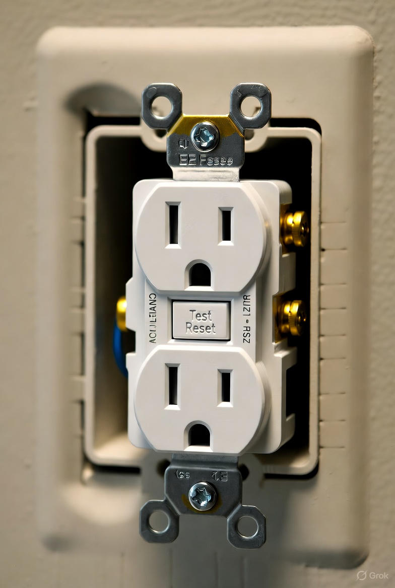
How to Wire a GFCI Outlet: A Step-by-Step NEC Guide
Answering Your Core Question: Wiring a GFCI Outlet
Learning how to wire a GFCI outlet correctly is a fundamental skill for any licensed electrician. The process hinges on proper identification and connection of wires to the correct terminals. After de-energizing the circuit, you must identify the incoming power source wires (the “line” side) and any wires continuing to other outlets (the “load” side). For basic GFCI protection at a single location, connect the hot and neutral power source wires to the LINE terminals only on the GFCI outlet, which are clearly marked. To protect downstream outlets, connect the outgoing wires to the LOAD terminals. This application of the ground-fault circuit interrupter is crucial for safety and compliance with NEC 210.8. Proper GFCI outlet wiring ensures the device can detect a ground fault and de-energize the circuit, preventing serious electrical shock.
The Critical Role of GFCI Protection in Electrical Safety
So, what is GFCI protection really about? The primary function of a GFCI receptacle is personnel protection. A ground-fault circuit interrupter constantly monitors the current flowing from hot to neutral. If it detects an imbalance as small as 4-6 milliamps—indicating that current is returning to ground through an unintended path (like a person)—it trips the circuit in a fraction of a second. This rapid response is what prevents severe injury or electrocution. The GFCI meaning is simple: it’s a life-saving device. You may also see the term gfi outlet; this is simply an older term for the same device. Understanding the difference between gfi vs gfci is just knowing they are synonymous. These devices, or gfcis, are a cornerstone of modern electrical safety.
GFCI vs. AFCI: Knowing the Difference is Key
A common point of confusion for apprentices—and even some seasoned pros—is the distinction between GFCI vs AFCI protection. While both are critical safety devices, they protect against entirely different hazards. As we’ve covered, GFCIs guard against electrical shock. An arc-fault circuit interrupter, or AFCI, is designed to protect against fire. An AFCI breaker or AFCI outlet detects the unique characteristics of a dangerous arc fault—a common cause of electrical fires—and de-energizes the circuit. This is different from a normal operational arc, such as flipping a switch.
Per NEC 210.12, most branch circuits in dwelling units must have AFCI protection. The choice between implementing this with an arc fault breaker or an arc fault receptacle (or arc fault interrupter outlet) depends on the specific branch circuit requirements and installation design. An AFCI circuit breaker protects the entire circuit, while an AFCI outlet provides protection from that point downstream. The same logic applies to a GFCI breaker versus a GFCI outlet. It’s not uncommon to see combination AFCI/GFCI devices, and the NEC often requires both types of protection, so understanding the afci vs gfci difference is non-negotiable for a qualified person.
Before You Begin: Tools, Materials, and Code Compliance
Before beginning any GFCI outlet wiring, a qualified person must ensure all work complies with the National Electrical Code (NEC). NEC 210.8 is the primary article outlining where GFCI protection is required in dwelling and non-dwelling units, including areas like a bathroom GFCI outlet, GFCI outlets in kitchen areas, garages, and any outdoor GFCI outlet. Always use listed and labeled devices. For specific applications, you may need a 20 amp GFCI outlet, a tamper-resistant receptacle (now required in most locations), or a weather-resistant (WR) receptacle for a GFCI outdoor outlet installation.
Key Tools and Materials:
- Voltage tester (non-contact and/or multimeter)
- Screwdrivers (flathead and Phillips)
- Wire strippers
- Pliers (lineman’s and needle-nose)
- The correct, listed GFCI outlet
How to Wire a GFCI Outlet: A Step-by-Step Guide
This section provides a detailed guide on how to wire a GFCI outlet. Following this process ensures safety and proper functionality, including providing downstream receptacle protection. A correct installation relies on understanding the line vs load GFCI connections.
- Safety First: De-energize the Circuit. Locate the correct breaker in the electrical panel and turn it off. Use your voltage tester to confirm there is no power at the outlet box. This is the most critical step.
- Identify Line and Load Wires. This is the key to correct wiring. The “LINE” wires are the incoming power source from the panel. The “LOAD” wires are those that continue on to feed other standard receptacles downstream. If the box only contains one set of wires, those are your LINE wires.
- Connect Wires to the LINE Terminals. Every GFCI receptacle has its terminals clearly marked. Connect the incoming hot wire (usually black) to the brass LINE terminal and the incoming neutral wire (white) to the silver LINE terminal. Connect the ground wire (bare copper or green) to the green ground screw. This configuration provides protection only at this GFCI outlet.
- (Optional) Connect Wires to the LOAD Terminals. For feed-through protection of downstream devices, connect the outgoing hot wire to the brass LOAD terminal and the outgoing neutral to the silver LOAD terminal. This means any regular receptacle connected to these wires will now have GFCI protection. This is a common and effective use of GFCIs.
- Install on an Ungrounded Circuit (per NEC 406.4(D)). For ungrounded circuit GFCI installation in older homes, you can replace a two-prong outlet with a GFCI. You will only connect the LINE wires. You must then apply the included “No Equipment Ground” and “GFCI Protected” labels to the face of the outlet and any downstream outlets you protect. This is a specific allowance under NEC 406.4(D).
- Consider Pigtail Wiring. If you’re installing a GFCI in the middle of a circuit run but do not want to protect the downstream outlets on that same circuit, use pigtail GFCI wiring. Connect the incoming and outgoing hot wires together with a short “pigtail” wire that connects to the GFCI’s LINE hot terminal. Do the same for the neutral wires on the LINE neutral terminal. The LOAD terminals are left empty.
- Secure and Test the Outlet. Carefully fold the wires into the box, secure the receptacle, and attach the faceplate. Turn the breaker back on. Press the “TEST” button—the “RESET” button should pop out. Then press “RESET”. If it holds, your installation is correct. Use a plug-in tester to check GFCI functionality. The official GFCI wiring diagram or GFCI outlet wiring diagram included with the device is your best reference.
Advanced Considerations for GFCI and AFCI Installations
Beyond a single receptacle, professional electricians must understand system-level protection. Choosing between a receptacle and a breaker device like a GFCI circuit breaker or AFCI circuit breaker often comes down to cost, convenience, and the level of protection required by the NEC for the specific branch circuit requirements. For instance, a high-amperage circuit might require a 30 amp GFCI breaker. When installing an arc detector breaker, like a popular Eaton arc fault breaker, it’s important to understand the terminal connections. The answer to how many wires are connected to a single-pole AFCI breaker is typically three: the load hot wire connects to the breaker’s load terminal, the load neutral wire connects to the breaker’s neutral terminal, and the breaker’s coiled pigtail connects to the panel’s neutral bus. This allows the breaker to monitor the entire circuit’s neutral path. Furthermore, as required by UL 943 standards since 2015, all modern gfi outlets must be of the self-testing GFCI type, which automatically conduct periodic internal tests.
Key Professional Considerations:
- NEC Updates: The NEC is updated every three years. Understanding GFCI requirements for non-dwelling locations is critical for commercial work.
- Replacements & Refurbishing: There are specific rules governing GFCI and GFPE receptacle replacements. Additionally, the NEC has clear guidelines on refurbishing GFCIs and other electrical equipment—generally, it’s prohibited.
- Specialty Equipment: Unique applications, such as welders, have their own requirements. Staying current on how the 2023 NEC requires GFCI protection for welders is essential for industrial electricians.
Troubleshooting: Why Your GFCI Keeps Tripping
A common service call is for a “GFCI keeps tripping“. This can be caused by a genuine ground fault, a faulty appliance, accumulated moisture, or a wiring issue. One common complaint is, “my espresso machine keeps tripping GFCI outlet.” This is often due to leakage current inherent in the heating elements of some appliances. To troubleshoot, unplug everything from the circuit and reset the GFCI. If it holds, plug in appliances one by one to find the culprit. If it trips with nothing plugged in, the fault is in the wiring itself. To determine how to know when GFCI is bad, if it won’t reset with no load attached or fails the “TEST/RESET” procedure, it’s likely time for a replacement. For portable needs, an extension cord with GFCI or a standalone GFCI plug can provide temporary protection.
Ready to become an expert in the latest code changes? Master GFCI and AFCI requirements with our NEC Code Changes course.
Primary Sources for NEC Compliance
For the most current and official code text, always refer directly to the source. The National Electrical Code (NEC) is published by the National Fire Protection Association (NFPA).
Frequently Asked Questions about GFCI Wiring
What is the difference between the line and load terminals on a GFCI receptacle?
The “LINE” terminals are for the incoming power wires from the circuit breaker panel. The “LOAD” terminals are for outgoing wires that feed other standard outlets, providing them with feed-through protection. Understanding the line vs load gfci connection is the most critical part of a proper installation.
Can I install a GFCI outlet on a circuit with an AFCI breaker?
Yes, this is a common and often required practice. The AFCI breaker (or other arc fault breakers) provides arc-fault protection for the entire circuit, while the GFCI outlet provides ground-fault shock protection at the point of use and downstream. They serve different safety functions and do not interfere with each other. This combination provides the highest level of safety.
How do I replace a regular outlet with GFI outlets on an ungrounded circuit?
As per NEC 406.4(D), you can perform an ungrounded circuit GFCI installation. You connect the hot and neutral wires to the LINE terminals only. The ground screw is left unconnected. Crucially, you must apply the “GFCI Protected” and “No Equipment Ground” labels to the face of the GFCI receptacle. This is a safe and code-compliant way to upgrade safety in older wiring systems that lack a ground wire.
Continuing Education by State
Select your state to view board-approved continuing education courses and requirements:
Disclaimer: The information provided in this educational content has been prepared with care to reflect current regulatory requirements for continuing education. However, licensing rules and regulations can vary by state and are subject to change. While we strive for accuracy, ExpertCE cannot guarantee that all details are complete or up to date at the time of reading. For the most current and authoritative information, always refer directly to your state’s official licensing board or regulatory agency.


