How to Wire a Duplex Receptacle: Step-by-Step Guide
Properly wiring a duplex receptacle is a fundamental skill for any licensed electrician. Knowing how to wire a receptacle outlet correctly ensures safety, code compliance, and reliable performance. This guide provides an expert walkthrough of the process, covering everything from understanding the hot neutral ground wire color code to adhering to NEC standards. The core procedure involves de-energizing the circuit, stripping the NM-B cable, and making secure connections: the black (hot) wire to the brass terminal, the white (neutral) wire to the silver terminal, and the bare copper or green (ground) wire to the green grounding screw. This correct receptacle wiring is crucial for any standard 120v outlet. Following these steps meticulously for every duplex receptacle installation is the hallmark of a professional.
Understanding the Fundamentals: Receptacle vs Outlet and Key Definitions
In the electrical trade, precise terminology is critical. While clients may use “outlet” and “receptacle” interchangeably, the National Electrical Code (NEC) provides a clear distinction. Answering “what is an outlet?” from a code perspective is essential. The NEC’s outlet definition is a point on the wiring system at which current is taken to supply utilization equipment. This could be a light fixture, a smoke detector, or a receptacle.
The receptacle definition, on the other hand, is a contact device installed at the outlet for the connection of an attachment plug. So, an electrical receptacle is a specific type of outlet. Understanding this receptacle meaning clarifies that every receptacle is an outlet, but not every outlet is a receptacle. To define receptacle properly is to identify it as the device that an electrical plug connects to. The plural form, receptacles definition, simply refers to multiple such devices. It is critical to select a receptacle with the proper type and rating for its specific application.
Essential Pre-Installation Checks: Safety and NEC Compliance
Before beginning any electrical outlet installation, safety and code compliance are paramount. Always de-energize the circuit at the breaker panel and use a non-contact voltage tester to confirm there is no power. A key pre-installation step is performing an electrical box fill calculation per NEC Article 314.16 to ensure the box is not overcrowded with conductors and devices.
Adherence to NEC receptacle requirements is non-negotiable. This includes proper circuit protection, such as AFCI circuit protection, which is required for circuits supplying outlets in most dwelling unit locations. Furthermore, always use UL listed wiring devices to ensure they have been tested for safety and performance by a Nationally Recognized Testing Laboratory. The professional standard is to never install a power outlet without verifying these critical safety and compliance checks.
Primary Sources for E-E-A-T
This guide is based on established best practices and standards from leading authorities in the electrical industry. For direct reference, consult:
- NFPA 70, National Electrical Code (NEC): The benchmark for safe electrical design, installation, and inspection.
- Underwriters Laboratories (UL): For standards and certification of wiring devices and electrical equipment.
Step-by-Step Guide: How to Wire a Receptacle Outlet
Following a methodical process for every outlet on wall ensures a safe and durable connection. This numbered list details the professional standard for wiring a common 120 volt outlet.
- De-energize and Verify: Turn off the corresponding circuit breaker and apply a lockout/tagout device. Use a reliable voltage tester to verify the circuit is dead at the outlet box.
- Prepare the NM-B Cable: For standard NM-B cable wiring, carefully strip approximately 6–8 inches of the outer sheathing. Then, using a wire stripper, remove about 3/4 inch of insulation from the black (hot) and white (neutral) conductors.
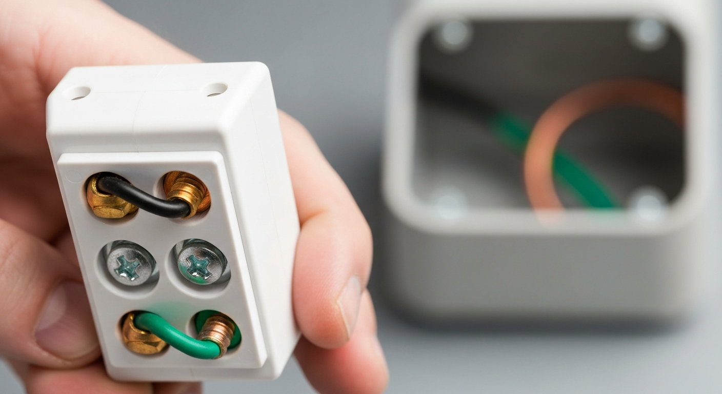
- Identify Wires: Confirm the hot neutral ground wire color code: the black wire is hot, the white wire is neutral, and the bare copper or green wire is the equipment grounding conductor.
- Make the Grounding Terminal Connection: Create a J-hook in the bare copper ground wire and loop it clockwise around the green grounding screw on the receptacle. Tighten the screw securely. This is a critical safety connection.
- Connect the Neutral Conductor: Create a J-hook in the white neutral wire and loop it clockwise around one of the silver-colored neutral terminal screws. Tighten the screw.
- Connect the Hot Conductor: Create a J-hook in the black hot wire and loop it clockwise around one of the brass-colored hot terminal screws. Tighten the screw. Clockwise loops ensure the wire tightens under the screw head.
- Secure and Torque Terminals: Gently tug on each wire to ensure a solid mechanical connection. Adhering to manufacturer-specified receptacle torque specifications is vital for preventing loose connections and potential fire hazards. Understanding how 2023 NEC changes affect receptacle termination types and ratings is crucial for modern installations.
- Mount and Energize: Carefully fold the wires into the box and screw the receptacle to the box. If the wall finish is thick, an outlet box extender may be needed. Attach the faceplate, restore power at the breaker, and test the power outlet with a circuit tester.
Common Receptacle Types and Wiring Considerations
While the basic duplex outlet is common, professionals must be adept at handling various types and wiring methods.
15A vs 20A Receptacle Wiring
The wiring difference between 15A and 20A branch circuits is primarily conductor size and circuit protection. A 15A branch circuit uses 14 AWG copper conductors and 15A devices; a 20A branch circuit requires 12 AWG copper conductors. Note that while a 20A-only (T-slot) receptacle must never be installed on a 15A circuit, the NEC does permit 15A receptacles on 20A general-purpose branch circuits in many cases — the difference is important for compliance and device selection.
Side Wire vs Back Wire Terminals
The side-screw terminal method (screw clamping) is the most secure and preferred method for terminating conductors. “Back-stabbing” (push-in spring terminals) is allowed only on listed devices and is limited in application (commonly permitted on 15A receptacles using solid 14 AWG copper conductors). For critical or heavy-duty installations, use the side-screw terminals or pressure-plate style back wiring listed for the conductor size.
Pigtailing Electrical Outlets
The practice of pigtailing electrical outlets is a superior method for wiring multiple receptacles in a single circuit. Instead of feeding conductors through each device, a short “pigtail” wire connects from the main circuit conductors to the receptacle. This ensures that a failure at one electric outlet does not interrupt power to downstream devices.
GFCI and Tamper-Resistant Receptacle Code
A GFCI receptacle installation is required in locations like bathrooms, garages, kitchens, and outdoors to protect against shock hazards, and those location requirements are spelled out in the NEC. Similarly, the tamper-resistant receptacle code mandates listed tamper-resistant receptacles in dwelling unit locations and other specified areas — installers should follow NEC 406.12 for the exact locations where tamper-resistant devices are required. For additional detail, refer to the 2023 NEC requirements for tamper-resistant receptacles.
Advanced and Specialty Receptacle Applications
Beyond the standard 120 vac outlet, electricians often encounter specialty applications that require specific knowledge.
- High-Amperage Outlets: This includes a dedicated dryer outlet (typically a NEMA 14-30), a nema 14-50 outlet for electric ranges or a 50 amp rv receptacle. This is often just called a 14-50 outlet. These require larger gauge wire and are wired for 240V.
- Kitchen and Countertop Outlets: A kitchen outlet has specific spacing requirements. A countertop outlet or kitchen island outlet may be a standard decora outlet, or it could be a specialized pop up counter outlet. For a clean look, an under cabinet outlet strip or other under cabinet outlets are popular choices.
- Specialty Locations: A floor receptacle must have a specific cover assembly. An outlet inside wall, such as for a wall-mounted TV, requires a recessed box. For any electricity receptacle exposed to the elements, proper installation of weatherproof or wet location-rated receptacles is essential.
- Unique Wiring and Designer Devices: An isolated ground receptacle provides a separate grounding path for sensitive electronic equipment; a split-wired receptacle can be used where one half is switched. For premium projects, designer series devices such as Decora-style receptacles from major manufacturers provide both function and aesthetics.
A proper electrical outlet installation is more than just connecting wires; it’s about a deep understanding of the code, materials, and applications. From a simple 110 volt outlet (an older term for a 120V outlet) to a complex appliance connection, mastery is key. While an extension cord with multiple outlets is a temporary consumer solution, a permanently installed outlet on wall is the safe, compliant alternative. The connection of a 120v plug to a well-installed receptacle is the final step in a process demanding expertise.
Mastering these concepts, from the basic duplex outlet wiring diagram to the nuances of a dishwasher outlet, is what separates an apprentice from a journeyman. Before tackling your next project, ensure your knowledge is current. Master the fundamentals of residential wiring with our core competency courses.
Key Takeaways for Professional Receptacle Installation
- Safety First: Always de-energize and verify a circuit is dead before beginning work.
- Code is King: Adhere strictly to all NEC receptacle requirements, including AFCI/GFCI protection and box fill.
- Polarity and Grounding: Always follow the correct hot neutral ground wire color code and ensure a solid grounding terminal connection.
- Secure Connections: Use side-screw terminals, create clockwise J-hooks, and torque to manufacturer specifications to prevent hazards.
- Use Listed Devices: Only install UL listed wiring devices to ensure safety and compliance for all electrical receptacles.
Frequently Asked Questions (FAQ)
What is the difference between a receptacle vs outlet according to the NEC?
According to the NEC, an “outlet” is a broad term for any point on a circuit where power is taken to supply equipment. A “receptacle” is a specific type of outlet—it’s the contact device where you plug in a cord via an electrical plug. Therefore, a light fixture can be an outlet, but only the device with slots is a receptacle.
Can I use back-wire terminals for 15A vs 20A receptacle wiring?
While some receptacles allow push-in (back-wire) terminations, NEC limits their application (commonly to 15A receptacles with 14 AWG solid copper conductors). For 20A circuits and larger conductors, use side-screw terminals or listed pressure-plate terminations. The most reliable and code-safe approach is to use the side screws for secure mechanical connections.
What are the most important NEC receptacle requirements for a standard duplex receptacle installation?
For a standard duplex receptacle, key NEC requirements include: proper AFCI circuit protection for dwelling locations (where required), GFCI protection for wet/damp locations (kitchens, baths, garages), adherence to the tamper-resistant receptacle code for dwelling units, correct box fill calculations per Article 314, and proper conductor sizing for the circuit’s amperage. Knowing how to wire a receptacle outlet to these standards is essential for a compliant installation.
Continuing Education by State
Select your state to view board-approved continuing education courses and requirements:
Disclaimer: The information provided in this educational content has been prepared with care to reflect current regulatory requirements for continuing education. However, licensing rules and regulations can vary by state and are subject to change. While we strive for accuracy, ExpertCE cannot guarantee that all details are complete or up to date at the time of reading. For the most current and authoritative information, always refer directly to your state’s official licensing board or regulatory agency.
NEC®, NFPA 70E®, NFPA 70®, and National Electrical Code® are registered trademarks of the National Fire Protection Association® (NFPA®)
You may also like

Colorado Electrical Licensing Requirements and Reciprocity Guide

Standby Generators in DE: Navigating Coastal Storm Regulations
