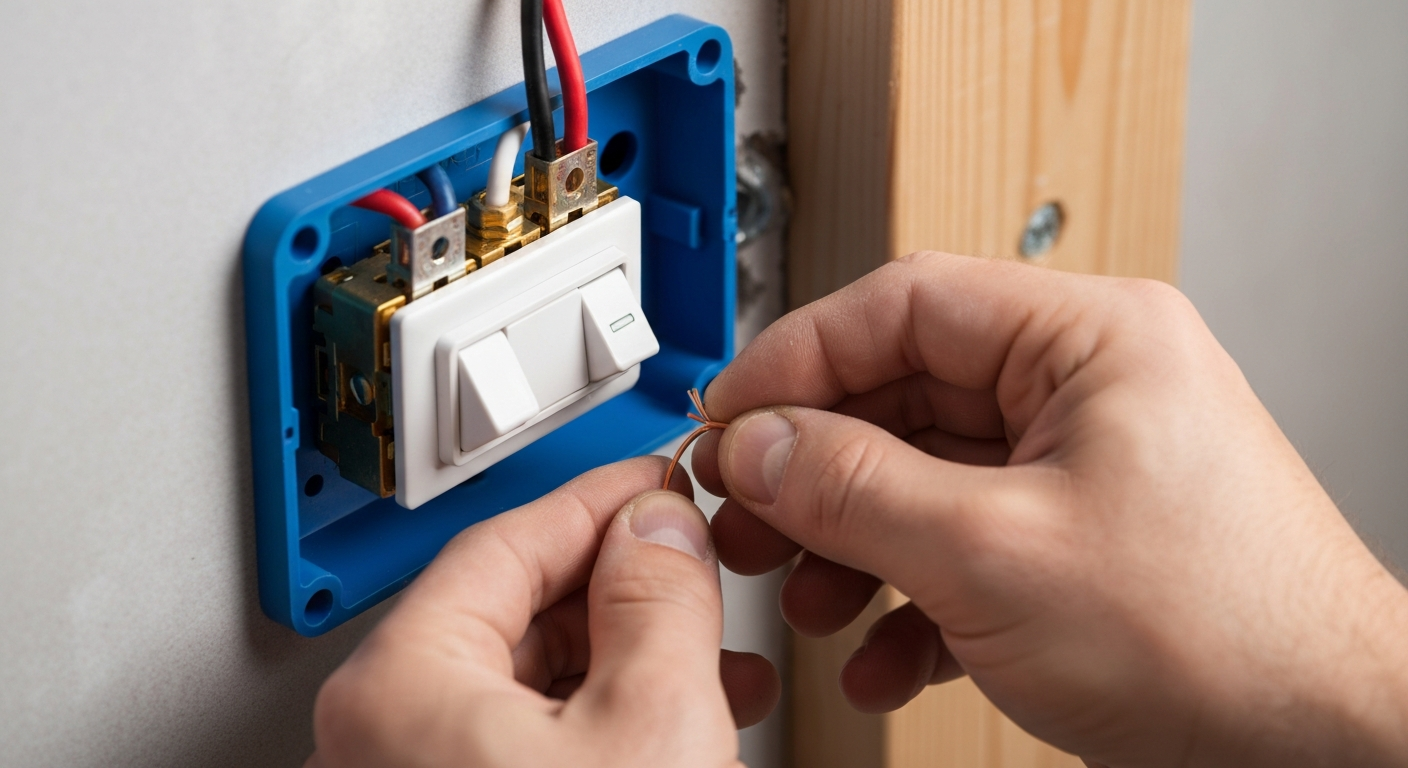
How to Wire a Dead-End 3-Way Switch: Wiring Diagram
Quick Answer: Wiring a Dead-End 3-Way Switch
Wiring a dead end 3 way switch, also known as an end of the run 3 way switch, involves a specific configuration where one switch box is the final point in the circuit’s cable run. In the most common modern method, power enters the first switch box (the “line” side). The hot wire connects to the common terminal of the first switch. A 3-wire cable then runs to the dead-end switch box; the two travelers connect to the traveler terminals on both switches. At the dead-end switch, the common terminal connects to the switched leg, which runs to the light fixture. Crucially, per NEC 404.2, a neutral wire in switch box locations is required for most new installations, which is carried through on the 3-wire cable. Proper common terminal wiring is the key to a functional installation, distinguishing the constant hot (or switched leg) from the travelers.
Understanding the Dead-End 3-Way Switch Configuration
For professional electricians, mastering multi-location switching is a fundamental skill. The 3-way switch is a cornerstone of this practice, allowing control of a single luminaire or outlet from two separate locations. While functionally a single pole double throw switch, its application can vary significantly based on how power is routed through the circuit.
This brings us to the core distinction between a feed-through vs dead-end switch. In a feed-through setup, the switch box contains both the incoming power source and an outgoing cable that continues on to power other devices downstream. In contrast, a dead end 3 way switch is the last device in that particular branch of the circuit. The cable entering its box is solely for the purpose of controlling the light; power does not continue on from that box.
NEC Compliance and the Dead-End Switch: A Look at NEC 404.2
The National Electrical Code (NEC) provides the minimum safety standards for all electrical installations, and switch wiring is no exception. A critical code section impacting this work is NEC 404.2, which mandates the presence of a neutral wire in switch box locations for most new construction and major renovations. This requirement ensures that a grounded conductor is available to power electronic lighting control devices like smart switches, dimmers, and occupancy sensors, which require a small amount of continuous power.
When wiring an end of the run 3 way switch, this rule is easily satisfied by using a 3-wire cable (e.g., 14/3 NM cable) between the two switch locations. This allows one conductor for the neutral to pass through, ensuring your work results in an NEC compliant 3 way switch installation. Staying current on these regulations is paramount for any licensed electrician. To learn more about how code changes affect your work, it’s vital to review the recent NEC updates on lighting and switch requirements.
Step-by-Step: Power to Switch Wiring for a Dead-End Configuration
This guide details the most common and code-compliant method where the power source feeds the first switch, and the dead-end switch controls the load (light fixture). This approach defines the line and load side of the circuit and uses a standard switched leg configuration from the second switch.
- Preparation and Safety: De-energize the circuit at the breaker and verify with a multimeter. At each switch box, identify your cables: the power source (typically 14/2 or 12/2), the cable between switches (14/3 NM cable), and the cable to the light fixture from the second box (14/2 or 12/2).
- Wiring the First Switch Box (Line Side): This box contains the incoming power.
- Connect the black (hot) wire from the power source cable to the common terminal wiring screw on the first 3-way switch. This screw is typically black or a darker color than the others.
- Connect the red and black conductors from the 14/3 cable to the two traveler terminals (usually brass-colored screws). These are your 3 way switch traveler wires.
- Splice the white (neutral) wire from the power source to the white (neutral) wire of the 14/3 cable. Push the connection to the back of the box.
- Connect all ground wires together and to the switch’s ground terminal.
- Wiring the Second Switch Box (Dead-End Load Side): This is your dead end 3 way switch.
- Connect the red and black conductors from the 14/3 cable to the two traveler terminals on the second 3-way switch.
- Connect the black wire from the cable going to the light fixture to the common terminal on this switch. This wire is the “switched leg.”
- Splice the white (neutral) wire from the 14/3 cable to the white (neutral) wire of the cable going to the light fixture.
- Ensure you are properly grounding switches and all devices in the box.
- Final Connections and Testing: At the light fixture, connect the black (switched leg) and white (neutral) wires accordingly. Secure all devices in their boxes, install faceplates, re-energize the circuit, and test for proper operation from both switch locations.
Key Considerations for Dead-End Switching
Even for seasoned professionals, a quick review of best practices is always beneficial. Keep these points in mind during your installation:
- Common Terminal Identification: Always correctly identify the common terminal. It is the pivot point of the switch and must be connected to the constant hot (at the first switch) or the switched leg (at the second switch). Mixing it up with a traveler is the most common error.
- Traveler Wires: The two 3 way switch traveler wires are interchangeable on their respective brass-colored terminals. Their function is simply to carry power between the two switches.
- Conductor Terminations: A secure installation depends on solid connections. Ensure you are following best practices for proper snap switch terminations to prevent loose wires and potential hazards.
- Future-Proofing: By including the neutral wire in switch box locations as required by NEC 404.2, you are not only being compliant but also preparing the installation for future upgrades to smart home technology.
With these fundamentals covered, you can confidently tackle more advanced wiring. Master complex switching scenarios with our residential wiring courses.
Common Issues & 3 Way Switch Troubleshooting
When a new installation doesn’t work as expected, a systematic approach to 3 way switch troubleshooting is essential. If the light only works with the switches in a specific combination, the most likely culprit is incorrect common terminal wiring. You have likely placed a traveler wire on the common screw of one of the switches. If the breaker trips immediately, check for a grounded conductor inadvertently connected to a switch terminal or a short circuit within one of the boxes. Always start your troubleshooting at the power to switch wiring source and work your way through the circuit logically.
Expanding Your System: 4-Way Switch Integration
What if you need to control a light from three or more locations? This is where 4-way switch integration comes into play. A 4-way switch is installed physically and electrically *between* the two 3-way switches. The two traveler wires from the first 3-way switch connect to one pair of terminals on the 4-way switch. A second set of travelers then runs from the other pair of terminals on the 4-way switch to the traveler terminals on the final dead end 3 way switch. You can add as many 4-way switches as needed between the two 3-way switches to achieve the desired level of control.
Primary Sources & Further Reading
This article is written to be consistent with the standards set forth in the National Electrical Code. For official reference, professionals should consult the latest edition of NFPA 70, National Electrical Code®.
Frequently Asked Questions (FAQ)
- What is the main difference in feed-through vs dead-end switch wiring?
- The primary difference is circuit continuation. In a feed-through setup, the switch box also serves as a junction to send power to other outlets or lights downstream. In a dead end 3 way switch setup, the switch box is the final point; the wiring within it only serves the multi-location control of its designated load and does not feed power elsewhere.
- Why is a neutral wire in switch box now required for a dead end 3 way switch?
- A neutral wire in switch box locations is mandated by NEC 404.2 to provide a return path for the small amount of power needed by electronic devices like smart switches, dimmers, and sensors. This future-proofs the installation, even if a standard mechanical switch is installed initially.
- How do you identify the 3 way switch traveler wires and the common wire?
- The common wire connects to the common terminal, which is usually a black or dark-colored screw, set apart from the other two. The 3 way switch traveler wires connect to the other two terminals, which are typically brass-colored. In the wiring itself, the common wire is either the constant hot from the source or the switched leg going to the load, while the travelers are the two conductors (usually red and black in a 14/3 cable) running between the switches.
- Can I add a 4-way switch to a dead end 3 way switch circuit?
- Yes. Effective 4-way switch integration requires placing the 4-way switch(es) between the two 3-way switches. The travelers from the first 3-way switch will feed the 4-way, and a new set of travelers will run from the 4-way to the final dead end 3 way switch.
Continuing Education by State
Select your state to view board-approved continuing education courses and requirements:
Disclaimer: The information provided in this educational content has been prepared with care to reflect current regulatory requirements for continuing education. However, licensing rules and regulations can vary by state and are subject to change. While we strive for accuracy, ExpertCE cannot guarantee that all details are complete or up to date at the time of reading. For the most current and authoritative information, always refer directly to your state’s official licensing board or regulatory agency.


