How to Wire a 4-Way Switch: Adding Multi-Location Control
Understanding Multi-Location Switching: The Role of 3-Way and 4-Way Switches
In residential and commercial electrical work, providing convenient control over lighting is paramount. A standard single-pole switch offers one point of control. A 3-way switch circuit allows control from two locations. But what happens when you need three, four, or even more control points? That is precisely where the four way switch comes into play.
A common misconception is that you would use three three way switches for three locations, but this is incorrect. The fundamental principle of multi-location switching is that the circuit always begins and ends with a 3-way switch. The incoming power (line) connects to the common terminal of the first 3-way switch, and the switched leg to the fixture (load) connects to the common terminal of the final 3-way switch. Every switch placed between these two endpoints must be a 4-way switch. The crossover switch function of a 4-way switch simply toggles the connection between the two pairs of traveler wires, either passing them straight through or crossing them over, which is what makes or breaks the circuit.
Essential Components and Concepts for Wiring a 4-Way Switch
Before you begin any installation, it’s critical to understand the hardware and wiring principles involved. A proper understanding of a 3 way switch wiring diagram and how a 4-way switch integrates into it is foundational. This includes identifying terminals, understanding wire function, and planning your circuit layout.
Conductor Identification and Terminals
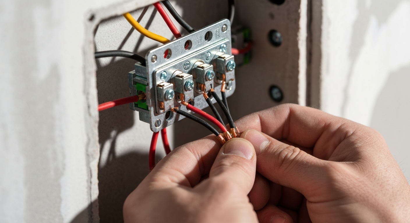
A key difference in this type of wiring is the distinction between common terminal vs traveler terminal.
- 3-Way Switch: Has three terminals. One is the “common” (usually a darker, black or brass-colored screw), which is the pivot point. This is where the line power enters the first switch or the load wire leaves the last switch. The other two terminals are for the traveler wires.
- 4-Way Switch: Has four terminals, typically arranged in pairs (two “in” and two “out”). There is no common terminal. These terminals are exclusively for connecting the two sets of traveler wires.
Proper conductor identification is crucial for a successful and safe installation. For the runs between switches, you will typically use NM-B cable with three insulated conductors plus a ground, such as 14/3 wire for switches on a 15-amp circuit. While the black and red conductors are used as travelers, the white (neutral) conductor may be re-identified when it’s used as an ungrounded conductor — for example by marking it per NEC rules at terminations — as permitted by code. Follow NEC marking rules (see Article 200) when re-identifying conductors.
Line and Load Side Wiring Explained
Understanding line and load side wiring is non-negotiable for any switch installation. The “line side” is where the power comes from the panel. The “load side” is the part of the circuit that runs from the final switch to the light fixture. The most common power source to switch configuration involves bringing the power feed into the first switch box. From there, a 3-wire cable carries the two travelers to the 4 way switch location, and another 3-wire cable runs from there to the final 3-way switch box. A separate 2-wire cable then carries the switched hot and neutral to the light fixture. Having a clear three way light switch wiring diagram to reference can prevent confusion.
Step-by-Step Guide: How to Wire a 4-Way Switch
This step-by-step process details the most common method for wiring a 3-way and 4-way switch combination. Always ensure the circuit breaker is turned off and verify the circuit is de-energized with a non-contact voltage tester before beginning work.
- Route Power to the First Switch Box: Run a 2-wire cable (e.g., 14/2 NM-B) from your power source to the first switch box. This is your line-side connection.
- Wire the First 3-Way Switch: Connect the incoming hot (black) wire to the common terminal of the first 3-way switch. Connect the red and black wires from your 3-wire cable (which will run to the 4-way switch) to the two traveler terminals. The specific terminal for each traveler doesn’t matter on a 3-way switch. Connect all neutral (white) and ground (bare copper/green) wires together in the box.
- Wire the 4-Way Switch: Run the 3-wire cable from the first box to the middle location. The switch 4 way wiring is critical. Connect the two incoming traveler wires (black and red) to one pair of terminals on the 4-way switch (e.g., the top two screws). Then, connect the two outgoing traveler wires from the next section of 3-wire cable (running to the final switch) to the other pair of terminals (e.g., the bottom two screws). Connect neutrals and grounds.
- Wire the Second 3-Way Switch: At the final switch box, connect the two traveler wires coming from the 4-way switch to the two traveler terminals on the final 3-way switch. Connect the black wire from the 2-wire cable that goes to the light fixture (the load) to the common terminal. This is a crucial step when you wire 3 way switch devices at the end of a circuit.
- Connect the Light Fixture: Connect the black (switched hot) and white (neutral) wires from the final switch box to the corresponding terminals on the light fixture. Ensure all ground wires are properly connected.
- Final Check and Energize: Double-check all connections against a reliable wire 3 way switch wiring diagram. Ensure all devices are securely mounted and cover plates are installed. You can now restore power and test all switch locations. This process for wiring 3way switches with an intermediate switch adds immense functionality.
Critical NEC Requirements and Best Practices
Adherence to the National Electrical Code (NEC) is mandatory. The process of wiring for 3 way switch diagram and 4-way switch circuits involves several key code considerations beyond just connecting wires.
NEC Requirements for Switching and Conductor Identification
The NEC lays out specific rules for multi-location control. The general NEC requirements for switching are found in Article 404. It’s essential to stay current with any amendments. For a deeper dive into recent code changes, you can explore ExpertCE’s lesson on how 2023 NEC updates have changed lighting, outlet, and switch requirements. One key rule is the requirement for a grounded conductor at many switch locations under Article 404.2(C), which facilitates the use of smart switches and other electronic devices. This is why running 3-wire cable between switches is now standard practice, even if older 3 way wiring methods did not require it.
Box Fill Calculations and Gangable Switch Boxes
With multiple cables entering a box, box fill calculations (NEC 314.16) become extremely important to prevent overheating and provide adequate space for devices. A 3-gang box housing three switches might contain independent circuits, but when wiring a multi-location setup, you might have two 3-wire cables and a device in a single box. You must correctly count conductors, devices, and clamps to ensure you don’t exceed the box’s capacity. Using a deep or gangable switch box can provide the necessary volume. Furthermore, the physical installation matters. Properly securing conductors is paramount; review the latest 2023 NEC rules on snap switch terminations to ensure compliance and a safe, durable connection. Finally, remember that switch placement is also regulated; you can learn more about how NEC 2023 has changed accessibility rules for circuit breakers and switches to ensure your installation meets all standards.
Common Issues and Troubleshooting a 4-Way Switch
Even for experienced electricians, troubleshooting 4-way switch circuits can be tricky. If the lights don’t work correctly from all locations, the issue almost always lies in the traveler wire connections. The most detailed three way switch wiring diagram won’t help if the physical connections are wrong.
- Incorrect Traveler Connections on 4-Way Switch: This is the most common problem. The travelers from the line-side 3-way must be on one pair of terminals (e.g., IN), and the travelers to the load-side 3-way must be on the other pair (e.g., OUT). Accidentally mixing these will cause the circuit to fail.
- Line or Load on a Traveler Terminal: The line hot (from the panel) and the load hot (to the fixture) MUST be on the common terminals of their respective 3-way switches. Connecting either to a traveler terminal will prevent the circuit from ever being completed correctly.
- Incorrectly Identified Wires: If you’re working with existing wiring or fail to label conductors during rough-in, you may misidentify a traveler, hot, or switched leg. This underscores the importance of a clear 3 way light switch diagram and methodical work.
- Faulty Switch: While less common, a switch itself can be defective out of the box. Use a multimeter to test for continuity in its different toggle positions if you suspect a bad switch. A good understanding of three way wiring principles makes diagnosis much faster.
Take your wiring skills to the next level with our advanced residential courses.
Primary Sources
This article is written to be consistent with best practices and standards set forth by the National Fire Protection Association (NFPA). For official code references, consult the latest edition of NFPA 70, National Electrical Code (NEC).
Frequently Asked Questions about Wiring a 4-Way Switch
- How does a 4-way switch differ from a 3-way switch?
- A 3-way switch has three terminals (two travelers and one common) and is used in pairs to control a load from two locations. A 4 way switch has four terminals (two pairs of travelers) and acts as an intermediate reversing switch. It is always installed between two 3-way switches to add a third or subsequent control point. It has no “common” terminal.
- Can I use a 4-way switch to replace a 3-way switch?
- No, they are not interchangeable. A 4-way switch cannot function at the beginning or end of a multi-location circuit because it lacks a common terminal for the main power feed (line) or the connection to the fixture (load). Correct 3 way switch wiring is required at the circuit’s ends.
- How do I correctly interpret a 4-way switch wiring diagram?
- A 4-way switch wiring diagram will show the power source entering the common terminal of the first 3-way switch. Two traveler wires will leave that switch and connect to one pair of terminals on the 4-way switch. A second set of travelers will leave the other pair of terminals on the 4-way switch and connect to the traveler terminals on the final 3-way switch. Finally, the common terminal of the last 3-way switch connects to the load. The diagram essentially shows a path interrupted and rerouted by each switch.
- What is the most common mistake when wiring a 3-way or 4-way circuit?
- The most frequent error in wiring 3 way switch and 4-way circuits is misidentifying or incorrectly connecting the conductors. Specifically, either landing the incoming hot wire or the outgoing load wire on a traveler terminal instead of the common terminal on a 3-way switch, or incorrectly pairing the traveler wires on the 4-way switch. A clear three way switch diagram like a wire diagram of 3 way switch is essential to avoid this.
Continuing Education by State
Select your state to view board-approved continuing education courses and requirements:
Disclaimer: The information provided in this educational content has been prepared with care to reflect current regulatory requirements for continuing education. However, licensing rules and regulations can vary by state and are subject to change. While we strive for accuracy, ExpertCE cannot guarantee that all details are complete or up to date at the time of reading. For the most current and authoritative information, always refer directly to your state’s official licensing board or regulatory agency.
NEC®, NFPA 70E®, NFPA 70®, and National Electrical Code® are registered trademarks of the National Fire Protection Association® (NFPA®)
You may also like

Colorado Electrical Licensing Requirements and Reciprocity Guide

Standby Generators in DE: Navigating Coastal Storm Regulations
