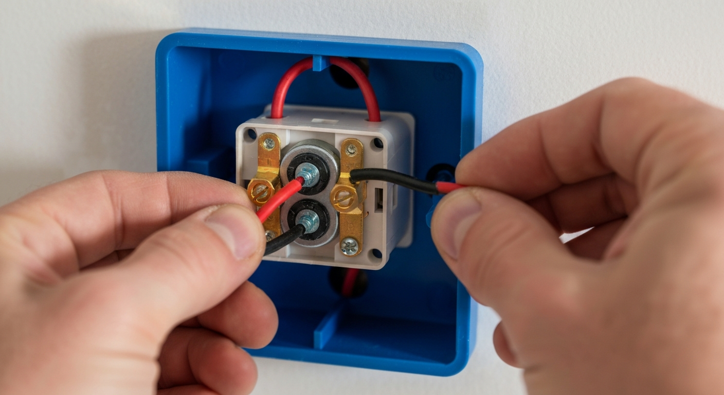
How to Wire a 3-Way Switch: A Beginner’s Guide with Diagrams
How to Wire a 3-Way Switch: A Beginner’s Guide with Diagrams
Answering Your Core Question: Wiring a 3-Way Switch
Learning how to wire a 3 way switch is a fundamental skill for any electrician, enabling control of a single light or load from two separate locations. The process hinges on correctly identifying and connecting specific conductors. Unlike a simple single-pole switch, a 3-way switch uses two special “traveler wires” that run between the two switches. The key is to connect the incoming power (line) to the unique “common terminal” on the first switch, and the wire going to the light fixture (load) to the common terminal on the second switch. The two traveler terminals on each switch are then connected to each other using a cable like a 14/3 cable. Always consult a proper 3-way switch wiring diagram and ensure your installation complies with the National Electrical Code (NEC) for safety and functionality.
Introduction to Multiple Location Switching
In residential and commercial electrical work, providing control over a lighting fixture from multiple points—such as the top and bottom of a staircase or both ends of a long hallway—is a common requirement. This is the core function of multiple location switching. While a standard switch provides simple on/off control from one spot, a 3-way switch circuit allows for this enhanced flexibility. Understanding these circuits is not just about convenience; it’s about executing a core competency of our trade with precision and safety. This guide will provide a comprehensive overview of the components, configurations, and best practices involved.
Understanding the Components of a 3-Way Switch Circuit
Before beginning any installation, it’s crucial to understand the components you’ll be working with. A 3-way circuit is more complex than a standard single-pole setup and requires specific parts and wiring knowledge.
The 3-Way Switch: A Specialized SPDT Switch
At its heart, a 3-way switch is a single-pole, double-throw (SPDT switch). This means it has one input terminal and can direct the current to one of two output terminals. The key terminals are:
- The Common Terminal: Usually identified by a black or dark-colored screw. This is the pivotal connection point. On one switch, it connects to the constant hot feed; on the other, it connects to the switched leg going to the load.
- Traveler Terminals: Two screws, typically brass-colored. These are interchangeable and connect to the two traveler wires that run between the switches.
Unlike a single-pole switch, a 3-way switch does not have “On” or “Off” markings, as its position is always relative to the other switch in the circuit.
Essential Conductors: Line, Load, and the Grounding Conductor
Correctly identifying your wires is paramount for safety and proper function. The main conductors you’ll encounter are:
- Line and Load Conductors: The “line” conductor is the wire bringing constant power from the source (breaker panel). The “load” conductor, also known as the switch leg, is the wire that carries power from the second switch to the light fixture.
- Travelers: These two conductors simply carry power between the two 3-way switches. They are only ever connected to the traveler terminals.
- Grounding Conductor: The bare copper or green-insulated wire is the equipment grounding conductor. It must be connected to the green screw on both switches and to the metal electrical box, if applicable. Proper grounding is a critical safety measure, and our guide on how to ground switches and receptacles per the NEC offers further detail.
Typically, a 14/3 cable (for 15-amp circuits) or 12/3 cable (for 20-amp circuits) is used between the switches to house the two travelers and a neutral conductor.
Common 3-Way Circuit Configurations
The layout of a building dictates the most efficient way to run wires. Understanding the different 3-way circuit configurations and knowing the hot feed location is essential for a code-compliant installation.
Standard Configuration: Power In at Switch 1, Out from Switch 2
This is the most straightforward and common setup. The power feed enters the first switch box, and the switch leg to the light fixture originates from the second switch box. Following a clear 3-way switch wiring diagram for this configuration simplifies the process.
Step-by-Step Wiring Process
- Safety First: De-energize the circuit at the breaker panel and verify with a multimeter that no voltage is present.
- Identify Conductors: In the first box (Box A), identify the incoming power cable (line) and the 14/3 cable going to the second switch. In the second box (Box B), identify the 14/3 from Box A and the cable going to the light fixture (load).
- Connect Switch A: Connect the black wire from the power feed (line hot) to the common terminal (black screw) of the first 3-way switch. Connect the red and black wires from the 14/3 cable to the two traveler terminals. Connect all neutral (white) wires together with a wire nut to maintain the circuit’s neutral path; they do not connect to the switch. Pigtail all ground wires together, connecting one lead to the switch’s ground screw and one to the box if it’s metal.
- Connect Switch B: Connect the black wire going to the light fixture (the switch leg) to the common terminal of the second 3-way switch. Connect the red and black traveler wires from the 14/3 cable to the two traveler terminals. Connect the neutral wires from the 14/3 cable and the cable to the light fixture together with a wire nut. Connect the ground wires as in the previous step.
- Final Connections: At the light fixture, connect the black wire (switch leg) to the hot terminal, the white wire to the neutral terminal, and the ground wire to the ground screw.
- Test the Circuit: Restore power at the breaker and test both switches to ensure they correctly control the light fixture.
The Dead End 3 Way Switch Configuration
A dead end 3 way switch, sometimes informally called a “California 3-way” (though this is not an official NEC term), occurs when the power feed and the switch leg to the light are in the same switch box. This method involves sending the constant hot feed to the second switch via one conductor, and using the other two conductors as travelers to bring the switched power back to the first box, where the light is connected. This junction box configuration can be confusing and often requires repurposing the white conductor in a cable to carry power, which must be permanently reidentified as a hot conductor as mandated by NEC 200.7(C). Adhering to the latest National Electrical Code (NEC) rules for conductor identification is especially important here.
Expanding to More Locations: 4-Way Switch Wiring
What if you need to control a light from three or more locations? This is where you integrate 4-way switches. The principle of 4-way switch wiring is to place one or more 4-way switches *between* the two 3-way switches. The two traveler wires from the first 3-way switch connect to one pair of terminals on the 4-way switch, and a second set of travelers runs from the other pair of terminals on the 4-way switch to the traveler terminals on the final 3-way switch. The 3-way switches always remain at the ends of the circuit.
Common Issues and 3-Way Switch Troubleshooting
Even seasoned professionals can make a mistake. Effective 3-way switch troubleshooting starts with a systematic approach to identifying the problem.
- Incorrect Common Terminal Connection: This is the most frequent error. If a traveler wire is connected to the common terminal, the circuit will only work when the switches are in a specific combination, or not at all. Always verify the line hot and switch leg are on the common terminals.
- Mixing Line and Load: Accidentally sending the load to the first switch and the line to the second will prevent the circuit from functioning.
- Loose Connections: A loose wire nut or a poorly seated wire on a terminal can cause intermittent or complete failure. Ensure all connections are mechanically and electrically sound.
- NEC Violations: Failing to re-identify a white conductor as a hot conductor when used as a traveler or switch leg can create a safety hazard and is a code violation under NEC 200.7(C). Keeping up with code is essential, especially with evolving requirements for lighting and outlets. Learn how the 2023 NEC updates have changed switch requirements to stay current.
Mastering these fundamental wiring techniques is a mark of a true professional. Build your confidence with fundamental wiring techniques. Explore our courses.
Primary Sources
For the most current and authoritative regulations, always refer to the official source for the National Electrical Code (NEC), published by the National Fire Protection Association (NFPA).
Frequently Asked Questions (FAQ)
- What is the most common mistake when learning how to wire a 3 way switch?
- The most common mistake is incorrectly identifying the common terminal on the switch. New electricians often connect one of the traveler wires to the common screw instead of the constant hot (line) or the switched hot to the fixture (load). This results in the lights only working when the switches are in a specific alignment, defeating the purpose of the circuit.
- Can I use a dead end 3 way switch configuration if power feeds the light fixture first?
- Yes, it’s possible, but it requires precise wiring. If the power source (hot feed location) is at the light fixture’s junction box, you must run a 3-wire cable to the first switch. One conductor (e.g., black) sends constant power down to the switch circuit, and another (white) provides the neutral. A second 3-wire cable is then run between the switches to house the two travelers and carry the neutral forward. The switched hot is routed back from the second switch, through the first switch box, and up to the light on the remaining conductor (e.g., red) in the first cable. This detailed management of line and load conductors is necessary to ensure a neutral is available at each switch location, as required by NEC 404.2(C) in most cases.
- What is the difference between 3-way switch wiring and 4-way switch wiring?
- 3-way switch wiring is used to control a load from two locations and always involves two 3-way switches. 4-way switch wiring is an addition to a 3-way circuit that allows for control from three or more locations. A 4-way switch is installed between the two 3-way switches, and you can add as many 4-way switches as needed to achieve the desired number of control points.
Continuing Education by State
Select your state to view board-approved continuing education courses and requirements:
Disclaimer: The information provided in this educational content has been prepared with care to reflect current regulatory requirements for continuing education. However, licensing rules and regulations can vary by state and are subject to change. While we strive for accuracy, ExpertCE cannot guarantee that all details are complete or up to date at the time of reading. For the most current and authoritative information, always refer directly to your state’s official licensing board or regulatory agency.


