How to Use a Multimeter to Test for Voltage (AC/DC)
How to Use a Multimeter to Test for Voltage (AC/DC)
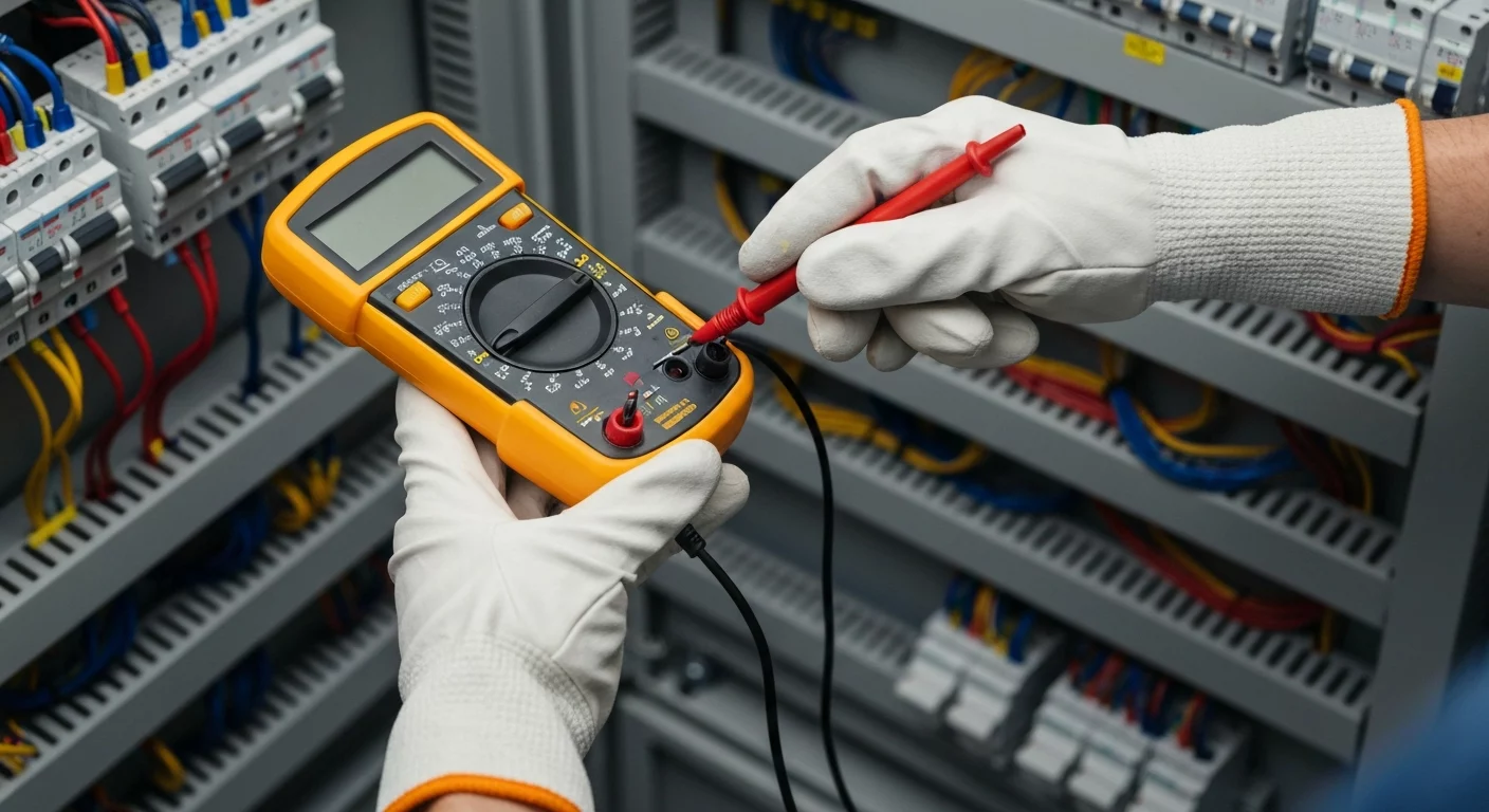
To properly test for voltage, you must first ensure safety by de-energizing the circuit and following NFPA 70E lockout/tagout procedures. After donning appropriate PPE, you must verify your multimeter is working using the “Live-Dead-Live” test. Select the correct function on your digital multimeter (DMM)—V with a wavy line (V~) for alternating current (AC) or V with a straight line (V⎓) for a DC source like a battery or DC motor. For unknown voltages, start with the highest range or use an auto-ranging meter. Insert the black probe into the COM jack and the red probe into the V/Ω jack. For AC voltage, touch the probes to the hot and neutral terminals; for DC, match red to positive and black to negative. The meter will display the voltage reading. Understanding the correct CAT rating and how to perform three-phase voltage testing are crucial skills for any journeyman electrician.
Understanding the Fundamentals: AC vs. DC Voltage
Before you can accurately test for voltage, it’s essential to understand the two fundamental types of electrical current you will encounter. Distinguishing between them is the first step in setting up your multimeter correctly and ensuring a precise measurement. The two primary forms are Alternating Current (AC) and Direct Current (DC). To dive deeper into their properties and applications, you can explore the differences between AC vs. DC current explained in detail.
- Alternating Current (AC): This is the type of electricity that powers homes and commercial buildings from the utility grid. Its direction and magnitude cycle periodically. When testing an AC source, such as a wall outlet or lighting circuit, you will always use the AC voltage setting on your meter.
- Direct Current (DC): DC flows in a single, constant direction. It is commonly found in batteries, solar panels, automotive systems, and electronic devices. Testing a DC motor supply or a low-voltage control circuit requires using the DC voltage setting. For a complete overview, see our guide to AC/DC current.
Safety First: NFPA 70E, CAT Ratings, and PPE
Testing for voltage is inherently hazardous. Adherence to NFPA 70E safety standards is not optional; it is a requirement for creating an electrically safe work condition. Before your hands ever touch a probe, a thorough risk assessment must be performed. This includes wearing the appropriate Personal Protective Equipment (PPE), which may consist of voltage-rated gloves, safety glasses or a face shield, and arc-rated clothing, depending on the potential for arc flash.
A critical, often overlooked, safety component is your multimeter’s CAT rating. This rating (e.g., CAT III, CAT IV) indicates the level of overvoltage protection the meter provides. These categories are defined by international standards like IEC 61010 to ensure user safety from transient voltage spikes in different electrical environments. Using a meter with an inadequate CAT rating for a high-voltage environment can lead to catastrophic failure and serious injury. For example, a CAT IV meter is required for work at the service entrance, while a CAT III is suitable for distribution panels. This is a core competency covered in advanced electrician training.
Safety first. Learn more about safe work practices in our NFPA 70E courses. Never assume a circuit is de-energized; always test to verify. Understanding the risks of working on energized electrical equipment is paramount.
How to Test for Voltage: A Step-by-Step Guide
For any professional, from apprentice to journeyman electrician, following a precise, repeatable process is key to safety and accuracy. This guide breaks down the essential steps for testing voltage with a digital multimeter (DMM).
- Verify Your Test Instrument: The first and most critical step is the “Live-Dead-Live” test. First, test your multimeter on a known live voltage source to ensure it’s working correctly. Second, test the circuit you are about to work on to confirm it is de-energized (reading zero volts). Finally, re-test your meter on the known live source to ensure it did not fail during the test. This process of verifying test instrument integrity is a cornerstone of NFPA 70E.
- Preliminary Check with a Non-Contact Tester: Before making contact, use a non-contact voltage tester (NCVT) to quickly check for the presence of AC voltage. While not a substitute for a multimeter reading, it provides an important initial layer of safety.
- Set the Multimeter Function: Turn the multimeter dial to the correct voltage type. For AC, select V~ or VAC. For DC, select V⎓ or VDC. Choosing the wrong type will result in an inaccurate or zero reading.
- Select the Voltage Range: If your meter is not auto-ranging, select a voltage range higher than what you expect to measure. For a standard 120V US outlet, you would select the 200V range or higher. Starting too low can damage the meter’s fuse or the meter itself.
- Insert Probes Correctly: Plug the black probe into the “COM” (common) jack. Plug the red probe into the jack labeled “V,” “Ω,” or “VΩ.” Never use the “A” (amps) jack for voltage measurements, as this can create a direct short and potentially an arc flash.
- Make Firm Contact: For an AC outlet, insert one probe into the hot slot (the smaller one) and the other into the neutral slot (the larger one). For DC circuits, touch the red probe to the positive (+) terminal and the black probe to the negative (-) terminal. Ensure the metal tips make solid, secure contact.
- Read and Interpret the Measurement: The meter’s display will show the measured voltage. A reading for a standard outlet should be between 110V and 125V. A reading of 0V after performing LOTO procedures confirms an electrically safe work condition.
Advanced Voltage Testing for the Journeyman Electrician
Beyond basic single-phase measurements, a skilled electrician must master more complex diagnostic techniques. These methods are crucial for troubleshooting commercial and industrial systems.
Three-Phase Voltage Testing: Line-to-Line and Line-to-Neutral
In three-phase systems, it’s essential to perform both line-to-neutral voltage and line-to-line voltage (or phase-to-phase measurement) tests. For a 120/208V system, you should measure ~120V from any phase to neutral and ~208V between any two phases (A to B, B to C, A to C). For a 277/480V system, these values will be ~277V and ~480V, respectively. Consistent readings across all phases are critical; an imbalance can indicate a serious problem. This type of Three-phase voltage testing is a daily task in industrial settings.
Troubleshooting Voltage Drop in a Circuit
Excessive voltage drop measurement can cause equipment to malfunction or fail. To perform a troubleshooting voltage drop test, measure the voltage at the source (e.g., the breaker) and then at the load (e.g., a motor) while the circuit is operating. The difference between these two readings is the voltage drop. NEC 210.19(A)(1) Informational Note No. 4 recommends sizing conductors to prevent a voltage drop of more than 3% for a branch circuit to ensure operational efficiency. However, it is important to remember that Informational Notes in the NEC are suggestions for best practice, not mandatory code requirements. Understanding concepts like a series vs parallel circuit is fundamental to diagnosing where the drop is occurring.
Identifying “Ghost Voltage” with a Low Impedance Multimeter
Have you ever tested a wire you know is de-energized but still get a reading of 50V? You may be seeing ghost voltage. This is a false reading caused by the capacitive coupling between energized and de-energized wires in close proximity. A standard high-impedance DMM is sensitive enough to pick up this phantom voltage. To get an accurate reading and dismiss it, use a low impedance multimeter (LoZ). This feature adds a small load to the circuit, which dissipates the ghost voltage, causing the meter to correctly read 0V.
Practical Application: Troubleshooting When a Breaker Keeps Tripping
A common service call is for a breaker keeps tripping. Voltage testing is a key diagnostic step. After ensuring the circuit is off, you can test for a short circuit by using the ohmmeter function. However, voltage tests are crucial to check for proper supply. A low voltage condition (a brownout) can cause equipment to draw more current, tripping the breaker. Conversely, a high voltage surge can also cause a trip. By checking the line voltage at the panel and at the affected receptacle, you can determine if the issue is with the power supply or a specific device on the circuit.
Key Considerations for Accurate Measurements
To ensure your readings are always reliable, keep these professional tips in mind. They are a core part of comprehensive electrician training and separate the novice from the expert.
- Probe Contact is Key: A loose or poor connection will give an erratic or incorrect reading. Ensure the metal tips of your probes are clean and make firm contact with the test points.
- Use Specialized Probes for High Energy: When measuring high voltage (typically over 600V), a standard multimeter is insufficient. A dedicated high-voltage probe is required to step down the voltage to a level the meter can safely handle.
- Verify Low-Voltage Control Circuits: When testing a control circuit voltage (often 24V AC or DC), be precise. An incorrect reading can lead to misdiagnosing expensive control boards or transformers.
- Always Start High: If you do not have an auto-ranging meter, always start your measurement on the highest voltage setting and work your way down to get a more precise reading. This prevents overloading the meter.
- Battery Check: A low battery in your multimeter can cause inaccurate readings. Most modern DMMs have a low battery indicator; pay attention to it.
Frequently Asked Questions (FAQ)
- What is the first step before I test for voltage?
- The absolute first step is safety. This involves conducting a risk assessment, wearing the correct PPE as dictated by NFPA 70E safety standards, and verifying your multimeter is functional with a Live-Dead-Live test. Safety always precedes any diagnostic measurement.
- How do you perform three-phase voltage testing?
- To perform three-phase voltage testing, you must measure between each phase and neutral (line-to-neutral voltage) and between each pair of phases (line-to-line voltage). For example, on a 120/208V system, you’ll check A-N, B-N, C-N (~120V each) and then A-B, B-C, A-C (~208V each).
- What causes ghost voltage and how do I get an accurate reading?
- Ghost voltage is a false reading caused by capacitive coupling from nearby energized conductors. It appears on high-impedance digital multimeters. To get a true reading and eliminate the ghost voltage, you must use a low impedance multimeter (LoZ) setting, which places a minor load on the circuit and dissipates the phantom charge.
- Why is the CAT rating on a multimeter important for a journeyman electrician?
- The CAT rating is a safety rating that indicates the maximum transient voltage the meter can withstand, as defined by standards like IEC 61010. A journeyman electrician works in diverse environments, from service entrances (CAT IV) to receptacles (CAT II). Using a meter with a CAT rating too low for the environment can lead to meter explosion and severe injury from transient overvoltage.
Continuing Education by State
Select your state to view board-approved continuing education courses and requirements:
Disclaimer: The information provided in this educational content has been prepared with care to reflect current regulatory requirements for continuing education. However, licensing rules and regulations can vary by state and are subject to change. While we strive for accuracy, ExpertCE cannot guarantee that all details are complete or up to date at the time of reading. For the most current and authoritative information, always refer directly to your state’s official licensing board or regulatory agency.
NEC®, NFPA 70E®, NFPA 70®, and National Electrical Code® are registered trademarks of the National Fire Protection Association® (NFPA®)
You may also like

Colorado Electrical Licensing Requirements and Reciprocity Guide

Standby Generators in DE: Navigating Coastal Storm Regulations
