Testing for Continuity with a Digital Multimeter: A How-To
Testing for Continuity with a Digital Multimeter: A How-To Guide
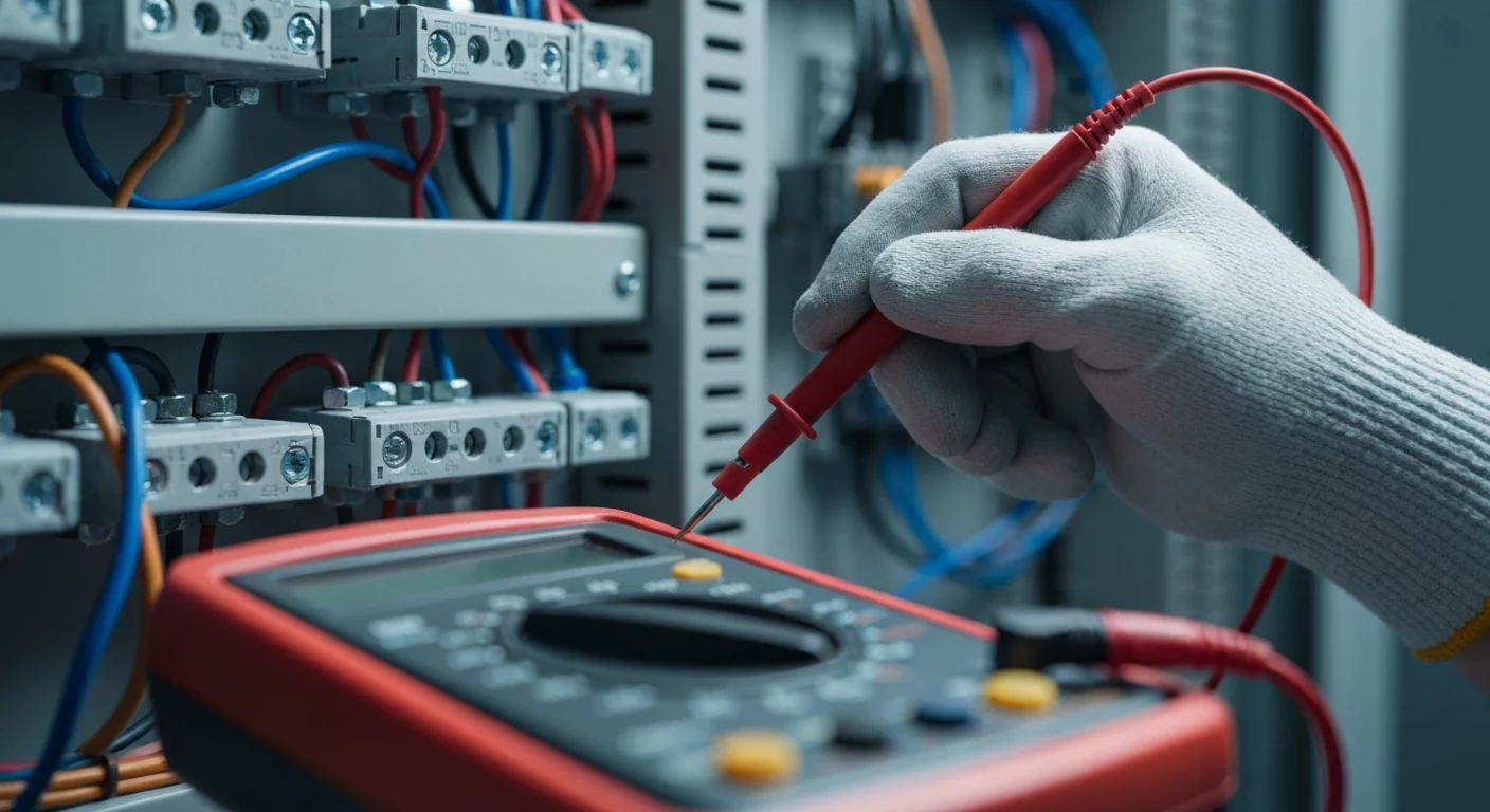
Testing for continuity is a fundamental skill in electrical troubleshooting, allowing you to determine if a continuous, unbroken path for current exists between two points. For any professional, from an apprentice to a seasoned journeyman electrician, mastering this diagnostic test is essential for quickly identifying issues like broken wires, faulty switches, or blown fuses. Using the continuity test mode on a digital multimeter (DMM), you can verify a closed circuit, indicated by an audible beep and a low resistance reading. This simple yet powerful procedure is a cornerstone of circuit diagnostics, helping to distinguish between an open circuit (a break in the path) and a complete path, ensuring the integrity and safety of electrical installations. A proper continuity test is always performed on a de-energized circuit to prevent damage to the meter and ensure personal safety.
What is Continuity in an Electrical Circuit?
At its core, continuity is the presence of a complete, unbroken path for electrical current to flow. Think of it like a lowered drawbridge—traffic can flow freely from one side to the other. In electrical terms, this is a closed circuit. When you are testing for continuity, you are checking for the existence of this bridge. If the test passes, it confirms there’s a good connection with very low resistance. Conversely, a lack of continuity signifies an open circuit—the bridge is up, and current cannot flow. This could be caused by a broken wire, a loose terminal, a blown fuse, or an open switch. Understanding this concept is the first step in effective electrical troubleshooting and is a foundational part of any comprehensive electrician training program.
Essential Tools and Electrical Safety Precautions
Before you begin, gathering the right tools and prioritizing electrical safety is paramount. You can’t perform a correct or safe test without them.
Required Tools
- Digital Multimeter (DMM): A quality DMM with a dedicated continuity test mode is essential. This mode is typically indicated by a symbol resembling a sound wave or diode.
- Test Leads: Your multimeter’s probes are your connection to the circuit. Ensure their insulation is intact and the tips are clean for accurate readings.
- Personal Protective Equipment (PPE): Always wear appropriate PPE, including safety glasses and insulated gloves, even when working on a circuit you believe is de-energized.
CRITICAL Safety Step: De-Energize the Circuit
Never attempt to test for continuity on a live or energized circuit. Performing a continuity test, which is a resistance-based measurement, on a circuit with voltage present can destroy your multimeter, create an arc-flash hazard, and cause serious injury. Always assume a circuit is live until you prove otherwise.
- Turn off the corresponding breaker in the electrical panel.
- Apply a lock and tag (Lockout/Tagout) to the breaker to ensure it cannot be re-energized accidentally.
- Use a non-contact voltage tester to confirm there is no voltage.
- Finally, set your DMM to AC voltage mode and test between hot and neutral, hot and ground, and neutral and ground to be certain you are working on a de-energized circuit.
How to Test for Continuity: A Step-by-Step Guide
With the circuit safely de-energized, you can proceed with the test. This process is a key part of circuit diagnostics for any working electrician.
- Step 1: Set Up Your Multimeter. Plug the black test probe into the COM jack (Common). Plug the red test probe into the VΩ jack (sometimes marked with V, Ω, and other symbols). Do not use the amperage (A) jacks.
- Step 2: Select Continuity Mode. Turn the rotary dial on your DMM to the continuity setting. The display should show “OL” or “1” for Over Limit, indicating an open circuit between the probes.
- Step 3: Test Your Meter. Before testing your circuit, touch the tips of the red and black test leads together. The multimeter should emit a continuous, audible beep, and the display should show a very low resistance value, typically less than one ohm. This confirms your meter, leads, and batteries are all functioning correctly.
- Step 4: Perform the Continuity Test. Place one probe at one end of the conductor or component and the other probe at the opposite end. For example, to test a light switch, you would place one probe on each of its screw terminals.
- Step 5: Interpret the Results.
- An audible beep and low resistance reading: This indicates a complete path for current. Continuity exists, and the component or wire is a closed circuit.
- No beep and an “OL” reading: This indicates a break in the circuit. There is no continuity, and you have an open circuit.
- An intermittent beep or a fluctuating resistance reading: This often points to faulty connections, corrosion, or a partially broken conductor. It suggests an unreliable path that could fail under load.
Practical Applications for the Journeyman Electrician
A journeyman electrician uses continuity testing daily to diagnose a wide range of problems. Here are some common applications:
- Checking Fuses and Breakers: A good fuse will have continuity, while a blown one will be an open circuit. While this test can identify an issue, recurring problems like a breaker that keeps tripping require deeper troubleshooting. For replacement guidance, see our guide on how to replace a circuit breaker.
- Verifying Conductors and Connections: Is a wire broken inside its insulation? Is a wire nut making a solid connection? Testing for continuity from end to end will instantly tell you if the path is intact.
- Testing Switches: This test is perfect for troubleshooting complex switch setups like 3-way switch wiring. You can confirm which terminals are connected in each switch position.
- Diagnosing Faulty Receptacles: While voltage tests are key, a continuity test on a de-energized circuit can help identify broken internal connections within an outlet. For more, see our tips on troubleshooting electrical receptacles.
- Identifying Wires: In a junction box with unlabeled wires, you can use a long test lead or a known ground to identify which wire goes where, although a dedicated circuit tracer is often more efficient for this task.
Expertise in these diagnostic methods is a must-have. Proper electrician training, like our hands-on guides and online electrical courses, can help you sharpen your skills. Improve your troubleshooting skills with our hands-on guides.
Continuity vs. Insulation Resistance Testing
It’s crucial not to confuse a continuity test with an insulation resistance test.
• A continuity test checks for a good, low-resistance path for current to flow through a conductor.
• An insulation resistance test, performed with a megohmmeter, checks for a very high-resistance path to ensure current does not leak between conductors or to ground. This tests the quality of the wire’s insulation. Proper wiring methods, as outlined in the NEC code book, are designed to ensure both conductor continuity and insulation integrity. For a detailed explanation of this advanced test, learn how to use a megohmmeter.
Key Takeaways for Accurate Continuity Testing
- Safety First: Always verify the circuit is a de-energized circuit before starting.
- Good is Low: A successful continuity test is indicated by an audible beep and a very low resistance reading.
- Open is “OL”: An “OL” (Over Limit) reading on your DMM signifies an open circuit with no continuity.
- Test Your Tool: Always touch your test leads together before the test to confirm the meter is working correctly.
- Interpret with Context: A reading of continuity is only “good” if the component is supposed to have it (e.g., a closed switch, a fuse). It’s “bad” if found where it shouldn’t be (e.g., a short circuit between hot and ground).
Frequently Asked Questions (FAQs)
What does it mean when testing for continuity gives no beep?
If your multimeter does not beep and the screen reads “OL” or “1”, it means there is an open circuit. This indicates a break in the electrical path you are testing, such as a broken wire, a blown fuse, or a switch in the open position.
Can I test for continuity on a live circuit?
No, absolutely not. Testing for continuity on a live circuit is extremely dangerous and can damage your meter. The continuity function is an ohmmeter-based test that sends a small current from the meter’s battery. Applying external voltage will overload the meter’s sensitive internal circuitry. Prioritizing electrical safety by working only on a de-energized circuit is critical.
How is a continuity test different from a resistance test?
The continuity test is a simplified, faster version of a resistance test. It provides a simple go/no-go result with an audible beep, ideal for quickly checking for a complete path. A resistance test, using the Ohms (Ω) setting, provides a specific numerical value of the resistance in the circuit. This is useful for more advanced circuit diagnostics, such as checking a resistor’s value or identifying high-resistance (but not fully open) faulty connections.
How does a series vs parallel circuit affect continuity testing?
In a series vs parallel circuit, the approach differs. To confirm continuity in a simple series circuit (e.g., a switch and a light), you must test the entire path. A single break anywhere will result in an open circuit. In a parallel circuit, you must isolate each branch to test it individually. Testing an entire parallel circuit at once can give misleading results, as current may still have a complete path through other branches even if one is open.
Continuing Education by State
Select your state to view board-approved continuing education courses and requirements:
Disclaimer: The information provided in this educational content has been prepared with care to reflect current regulatory requirements for continuing education. However, licensing rules and regulations can vary by state and are subject to change. While we strive for accuracy, ExpertCE cannot guarantee that all details are complete or up to date at the time of reading. For the most current and authoritative information, always refer directly to your state’s official licensing board or regulatory agency.
NEC®, NFPA 70E®, NFPA 70®, and National Electrical Code® are registered trademarks of the National Fire Protection Association® (NFPA®)
You may also like

Colorado Electrical Licensing Requirements and Reciprocity Guide

Standby Generators in DE: Navigating Coastal Storm Regulations
