How to Install a Service Mast and Riser: An NEC Guide
An Expert Guide to Service Mast Installation
A successful service mast installation is a fundamental task for any licensed electrician, blending structural integrity with strict adherence to electrical code. This critical electrical installation involves routing service entrance conductors from an overhead service entrance, through a conduit mast, to a meter base and service equipment. The process is governed primarily by NEC Article 230 and local utility company specifications, which dictate everything from conduit type to clearance heights. Proper installation commonly uses rigid metal conduit (RMC) because of its strength, but the NEC permits several conduit materials (galvanized steel, stainless steel, red brass, and aluminum under certain conditions). Regardless of material, ensure adequate conduit support and bracing, and correctly install a weatherhead to prevent water ingress. Mastering this process is essential for ensuring a safe, durable, and compliant connection to the electrical grid, forming the backbone of the entire building’s electrical system.
Understanding the Core Components of a Service Mast
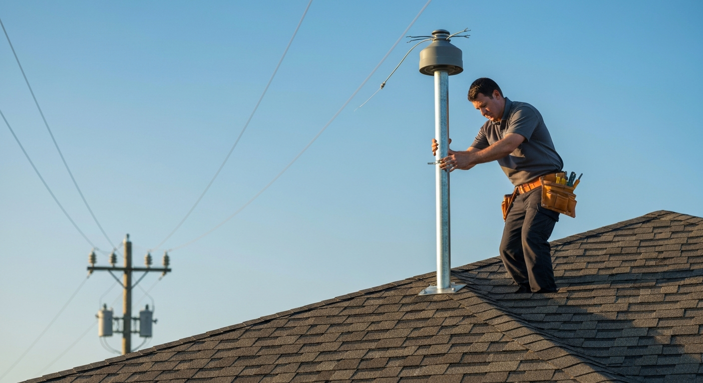
Before beginning any installation, it’s crucial to understand the components and their functions. A service mast is the rigid conduit assembly that extends through the roof or is attached to the side of a building to provide a secure attachment point for the utility’s service drop conductors. Unlike a service lateral, which involves underground conductors, the overhead service entrance relies entirely on the mast for structural support and conductor protection.
- Rigid Metal Conduit (RMC): RMC is commonly used for the service mast because of its strength and durability, but the NEC lists several permitted materials (galvanized steel, stainless steel, red brass, and aluminum with conditions).
- Weatherhead: A cap fitted to the top of the mast, designed to prevent rain and moisture from entering the conduit. A proper weatherhead installation is critical for long-term safety.
- Service Entrance Conductors: These are the wires running through the mast from the weatherhead to the meter base.
- Meter Base: The enclosure that houses the utility’s electric meter. Follow the local utility and AHJ mounting requirements for the meter base mounting.
Always begin by obtaining the latest utility company specifications. These documents often impose additional requirements beyond the NEC, especially concerning the point of attachment requirements and mast material or guying rules; utilities may require stricter or more prescriptive dimensions or mounting heights than the NEC.
Pre-Installation Planning: Your Blueprint for Success
Thorough planning, guided by an electrical riser diagram, is the key to an efficient and compliant installation. An electrical riser diagram provides a vertical representation of the electrical system, showing the path of conductors from the service equipment up to the weatherhead. This plan must account for all requirements in NEC Article 230, particularly those concerning clearances and support.
Critical Clearances and Attachment Points
Service drop clearance is a non-negotiable safety requirement detailed in NEC Article 230. Minimum clearances vary with the location beneath the drop and the voltage involved. Key points to verify on every job include:
- Over roofs: minimum vertical clearance above the roof surface is 8 ft 6 in. (2.6 m); certain exceptions allow reductions (for example to 3 ft / 900 mm) only when specific conditions in the code are met (including limits on conductor-to-conductor voltage and roof slope).
- Over sidewalks and pedestrian areas: minimum clearance is typically 10 ft (3.0 m) for services that meet the lower voltage-to-ground limits in the code.
- Over residential property and driveways: typical minimum clearance is 12 ft (3.7 m) where the voltage-to-ground limits specified by the NEC apply.
- Over public streets, alleys, or parking areas subject to truck traffic: higher clearances are required (for example 18 ft / 5.5 m in many conditions).
Equally important are the point of attachment requirements (NEC 230.26), which set minimum mounting heights for the attachment to a structure (for example a commonly used minimum for point-of-attachment to a building is about 3.0 m / 10 ft above finished grade) so that required clearances are maintained under conductor sag and other conditions. Always confirm exact clearance values for the voltage in question and applicable exceptions before cutting or fastening.
Step-by-Step Guide to Service Mast Installation
Executing a service mast installation is a precise process. Follow these steps for a compliant and secure result.
- Mount the Meter Base and Service Equipment: Begin with the meter base mounting according to the local utility and AHJ requirements; utilities commonly publish specific mounting heights but the NEC does not prescribe a single universal height. Install the main service panel and note the difference in terminology and application when considering a load center vs panelboard.
- Assemble and Install the Conduit: Assemble the rigid metal conduit sections that will form the service mast. Secure the conduit to the structure using appropriate straps and hardware, ensuring robust conduit support and bracing per the applicable conduit installation requirements.
- Manage a Through-the-Roof Penetration: If the mast penetrates the roof, a proper through-the-roof penetration is essential. Install a flashing boot or other approved roof penetration detail to create a watertight seal and follow the sealing requirements for raceways entering a building.
- Secure the Mast for Structural Loads: The mast must be strong enough to support the strain of the service drop. NEC 230.28 requires the mast to have adequate strength or be supported by braces or guy wires; local utility and AHJ rules may specify when guying or additional bracing is required depending on mast height and configuration.
- Pull Conductors and Install Weatherhead: Carefully pull the service entrance conductors through the mast. Perform the weatherhead installation, ensuring it’s positioned above the point of attachment per the NEC so the service drop can be landed correctly. Leave adequate conductor length for a proper drip loop formation to prevent water tracking into the weatherhead.
Terminating Conductors and Finalizing the Installation
Once the mast is secure, the conductors are terminated at the line side lugs of the meter base. The load side conductors then connect from the meter base to the main breaker in the service panel, energizing the electrical bus. A critical final step is ensuring all safety connections are made, especially the main bonding jumper. For grounded service systems the main bonding jumper (or equivalent connection) bonds the grounded service conductor to the equipment grounding conductor and the service equipment enclosure, establishing the low-impedance fault-current return path required for protection. Follow AHJ procedures for testing and verification before energizing.
This entire service assembly is a complex system. Electricians must be aware of regulations beyond the mast itself, such as the new requirements for outdoor emergency disconnects on dwellings. While a proper service mast is fundamental, a professional’s expertise must also cover specific load calculations like determining the correct hot tub wire size or installation details such as the proper garage outlet height.
Key Considerations for a Compliant Electrical Installation
Beyond the physical installation, several administrative and code-specific details are vital for project approval and safety.
- Utility vs. NEC: Always remember that local utility company specifications and the Authority Having Jurisdiction (AHJ) can impose additional or more specific requirements beyond the NEC. When in doubt, contact the utility’s engineering department and the local AHJ.
- Proper Labeling: With the 2023 code cycle, understanding how to comply with NEC service equipment labeling requirements remains important. All disconnects and service equipment must be clearly and durably marked as required by the code and AHJ.
- Service Disconnects: The rules for service disconnects can be complex; be sure you know how many service disconnecting means are allowed per service under the current NEC and local policies to avoid a failed inspection.
- Structural Integrity: Never underestimate the tension and weather loads on a service mast. Adhering to applicable mast guying requirements and manufacturer guidance is a critical safety measure to prevent damage to the structure.
Mastering these nuances is what separates a good electrician from a great one. Perfect your service installation skills with our in-depth NEC courses.
Primary Sources
- NFPA 70, National Electrical Code (NEC)
- Local Utility Company Electrical Service Requirements (ESR) Handbooks
Frequently Asked Questions (FAQ)
What are the primary NEC requirements for a service mast installation?
A compliant service mast installation must adhere to NEC Article 230. Key requirements include maintaining proper service drop clearance (see NEC 230.24) over ground, driveways, and roofs; meeting point of attachment requirements (NEC 230.26); and ensuring the mast has adequate structural support, including guying or bracing where NEC 230.28 or local requirements indicate it is necessary.
When are mast guying requirements necessary for a service mast?
Mast guying requirements follow NEC 230.28’s requirement that a mast be of adequate strength or be supported by braces or guy wires. Local utility specifications and AHJ rules commonly define when additional guying is required (for example, limits on unsupported mast height), so verify both NEC minimums and local standards on every installation.
What is the difference between an overhead service entrance and a service lateral?
An overhead service entrance involves service conductors running from a utility pole through the air to a service mast or other attachment point on the building. In contrast, a service lateral consists of service conductors that are buried underground, running from a utility pedestal or transformer to the building’s meter base, eliminating the need for a mast.
Continuing Education by State
Select your state to view board-approved continuing education courses and requirements:
Primary sources and local utility handbooks were consulted to verify these requirements. For additional guidance, refer to the NEC and your local utility’s specifications (for example the PG&E Greenbook) and always coordinate with the local Authority Having Jurisdiction (AHJ) before starting work.
Disclaimer: The information provided in this educational content has been prepared with care to reflect current regulatory requirements for continuing education. However, licensing rules and regulations can vary by state and are subject to change. While we strive for accuracy, ExpertCE cannot guarantee that all details are complete or up to date at the time of reading. For the most current and authoritative information, always refer directly to your state’s official licensing board or regulatory agency.
NEC®, NFPA 70E®, NFPA 70®, and National Electrical Code® are registered trademarks of the National Fire Protection Association® (NFPA®)
You may also like

Colorado Electrical Licensing Requirements and Reciprocity Guide

Standby Generators in DE: Navigating Coastal Storm Regulations
