How to Commission a Grid-Tied Solar Inverter: A Checklist
How to Commission a Grid-Tied Solar Inverter: A Checklist
To properly commission a solar inverter, a licensed electrician must systematically verify that all mechanical and electrical components are installed correctly, safely, and in accordance with the manufacturer’s specifications and all relevant National Electrical Code (NEC) solar standards. The process begins with rigorous safety protocols, including strict lockout/tagout (LOTO) procedures, followed by a detailed mechanical inspection. Key electrical tests for this grid-tied inverter setup include insulation resistance testing, polarity checks, and open-circuit voltage (Voc) testing on the DC side. The AC side is then verified for correct grid voltage and frequency before a controlled, sequential power-up. Finally, functional tests using an AC/DC clamp meter and manufacturer-specific solar inverter commissioning software confirm the system is performing to design specifications and is compliant with all utility interconnection requirements before it is officially handed over to the client.
The Critical Role of Inverter Commissioning
The solar industry is expanding rapidly, and with this growth comes an increased focus on quality control and long-term asset performance. For a professional journeyman electrician or electrical contractor, the commissioning process is the final and most critical quality assurance step in a grid-tied inverter setup. It is more than just “flipping the switch”; it is a methodical verification that transforms an assembly of components into a safe, efficient, and reliable power plant. Improper commissioning can lead to underperformance, premature equipment failure, and significant safety hazards, including fire and electric shock. As the solar market grows, so do the career opportunities for qualified electricians who can master this essential skill set.
Pre-Commissioning Essentials: Safety and Preparation
Before any power flows, preparation and safety are paramount. Rushing this stage is a common but dangerous mistake. A disciplined approach here prevents accidents and ensures the subsequent steps are built on a solid foundation.
Safety First: Lockout/Tagout (LOTO) Procedures
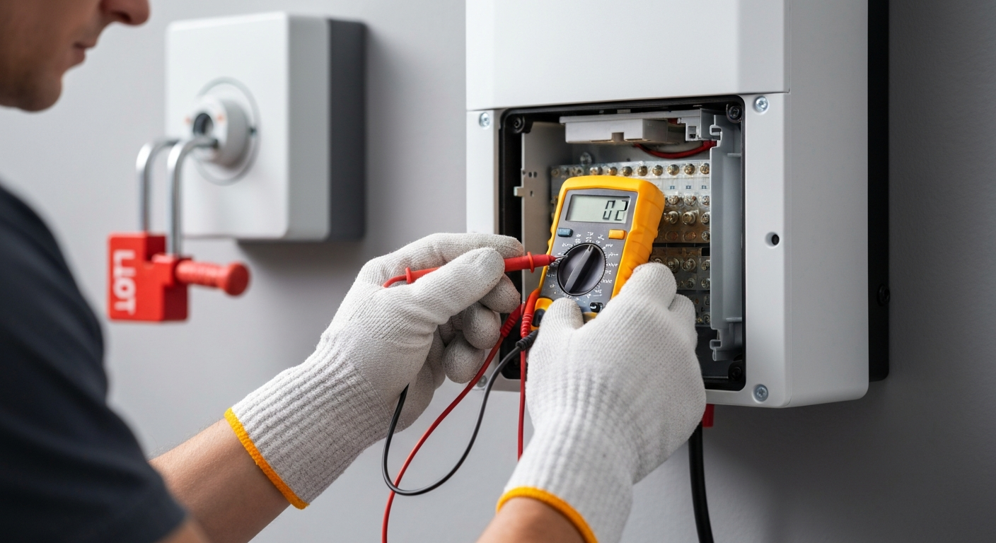
Before touching any electrical component, you must implement strict lockout/tagout (LOTO) procedures. According to OSHA, LOTO is a critical safety practice that prevents the unexpected energization of equipment during service. This involves isolating all potential energy sources—both from the PV array (DC side) and the utility grid (AC side)—and applying a lock and tag to each disconnecting means. Verifying the absence of voltage is a non-negotiable step in this process, as detailed in evolving safety standards like NFPA 70E. You can learn more about how NFPA 70E has changed voltage verification in our dedicated course material.
Essential Tools and Documentation
Having the right tools is essential for accurate and safe commissioning. Your toolkit should include:
- Personal Protective Equipment (PPE), including insulated gloves and safety glasses.
- A calibrated digital multimeter for voltage and continuity tests.
- An AC/DC clamp meter to measure current without breaking circuits.
- A megohmmeter (insulation resistance tester) to check for potential ground faults.
- A torque wrench to verify all electrical connections meet manufacturer torque wrench specifications.
- Manufacturer’s installation manual and the latest edition of the NEC code book.
The Commissioning Checklist: A Step-by-Step Guide
Follow this systematic checklist to ensure a thorough and compliant commissioning process for any string inverter testing or central inverter setup.
- Mechanical and Visual Inspection
Start with a detailed visual inspection of the entire installation. Check that the inverter is securely mounted with adequate ventilation clearance to prevent overheating. Inspect all conduits, enclosures, and the main breaker panel for proper installation. Use a torque wrench to confirm that every electrical lug on both the AC and DC sides is tightened to the manufacturer’s specified value to prevent high-resistance points that can lead to arcing. - DC Side Verification (PV Array)
Before connecting the array to the inverter, you must perform several critical tests. This PV array verification ensures the “fuel source” for your inverter is healthy and correctly wired.- Insulation Resistance Testing: Using a megohmmeter, test the insulation resistance between the positive and negative conductors and ground for each string. A low reading signals a ground fault that must be located and repaired. The proper megohmmeter use involves applying a specified DC test voltage (as recommended by the equipment or module manufacturer) and ensuring the resistance is above the minimum threshold set by the manufacturer or industry guidance.
- Polarity Testing: Verify the polarity of every string with a multimeter. Connecting a string with reversed polarity can instantly damage inverter input components.
- Open-Circuit Voltage (Voc) Testing: Measure the Voc of each string and compare it to the expected value calculated from the module datasheets, adjusting for temperature. This test confirms the string has the correct number of modules and there are no wiring issues, such as a missed connection in the series vs parallel circuit design.
- AC Side Verification (Grid Connection)
With the AC disconnect open, verify the utility side. Use your multimeter to check the grid voltage and frequency at the point of connection. Ensure these readings are within the inverter’s specified voltage and frequency tolerances. Inspect the grounding electrode system, including the connection to the grounding electrode (grounding rod), and verify that the required overcurrent protective device (breaker or fuse) is correctly sized and installed in accordance with the inverter manufacturer’s instructions and applicable NEC requirements. - Initial Power-Up and System Startup
Follow the manufacturer’s specified startup sequence precisely. This typically involves closing the DC disconnect first, allowing the inverter to power on and perform self-diagnostics. Once the inverter display is stable and shows no faults, close the AC disconnect to allow synchronization with the grid. Many modern inverters use dedicated solar inverter commissioning software on a laptop or mobile device to configure grid parameters, monitoring settings, and view real-time data during this phase. - Functional and Performance Testing
With the system operational, it’s time to measure its performance. Use an AC/DC clamp meter to measure the DC current from each string and the total AC output current from the inverter. Compare these real-world values to the expected output based on current solar irradiance levels. It’s also crucial to test safety functions. This includes verifying rapid shutdown compliance by activating the rapid shutdown initiator and confirming that conductors de-energize to required levels within the time frame specified by NEC 690.12. - Final Documentation and Handover
Record all test results—Voc, insulation resistance, current readings, and torque values—on a commissioning sheet. Ensure all settings are configured according to local utility interconnection standards. Finally, walk the system owner through the operation of their new system, explaining how to interpret the inverter display and use any monitoring platforms.
Ensure a smooth and safe system startup every time. View our commissioning guides.
Key NEC Solar Standards for Inverter Commissioning
A deep understanding of the National Electrical Code (NEC) solar standards is not optional—it’s a requirement for a safe and compliant installation. Commissioning is where you verify adherence to these rules.
- NEC Article 690 (Solar Photovoltaic Systems): This is the primary article governing solar installations. It covers everything from circuit sizing and overcurrent protection to disconnecting means and grounding. For PV systems, NEC 690.41 addresses de ground-fault detection/interruption requirements, and 690.12 details the critical requirements for rapid shutdown of PV conductors.
- NEC Article 705 (Interconnected Electric Power Production Sources): This article provides the rules for safely connecting a power source like a solar PV system to a primary source, such as the utility grid. It dictates requirements for the point of connection, disconnects, and overcurrent protection to prevent back-feeding the grid during an outage.
- NEC Article 250 (Grounding and Bonding): Proper grounding is foundational to safety. During commissioning, you must verify that all metallic components, from module frames to the inverter chassis, are correctly bonded and connected to the grounding electrode system as required by Article 250.
Inverters are complex power electronics, in some ways similar to how a VFD (Variable Frequency Drive) controls a motor. Mastering the codes that govern their installation and operation is a key competency for any electrician working in renewables.
Frequently Asked Questions (FAQ)
What is the first step in a grid-tied inverter setup?
The absolute first step is ensuring safety through comprehensive lockout/tagout (LOTO) procedures on all potential power sources, including the AC grid disconnect and the PV DC disconnects. Before any tools are used or inspections begin, all circuits must be de-energized and verified to be at zero volts.
Why is open-circuit voltage (Voc) testing crucial when you commission a solar inverter?
Open-circuit voltage (Voc) testing is a critical diagnostic step that verifies the PV array is correctly wired. It confirms each string has the right number of modules and that there are no open connections. A reading that is too high or too low indicates a wiring error or a mismatch with the design that must be corrected before energizing the inverter, preventing potential equipment damage.
What does rapid shutdown compliance mean according to NEC solar standards?
Rapid shutdown compliance, as defined in NEC 690.12, is a safety requirement designed to protect first responders. It mandates that PV system conductors beyond a certain distance from the array must be de-energized to a safe voltage level within 30 seconds of initiating the shutdown. During commissioning, you must functionally test this system to ensure it operates as designed.
How does an AC/DC clamp meter help during inverter commissioning?
An AC/DC clamp meter is an indispensable tool that allows an electrician to safely measure current flow without disconnecting any wires. During commissioning, it is used to measure the DC current from each PV string to check for performance issues and to measure the final AC output current of the inverter to verify the system is generating the expected amount of power.
Continuing Education by State
Select your state to view board-approved continuing education courses and requirements:
Disclaimer: The information provided in this educational content has been prepared with care to reflect current regulatory requirements for continuing education. However, licensing rules and regulations can vary by state and are subject to change. While we strive for accuracy, ExpertCE cannot guarantee that all details are complete or up to date at the time of reading. For the most current and authoritative information, always refer directly to your state’s official licensing board or regulatory agency.
NEC®, NFPA 70E®, NFPA 70®, and National Electrical Code® are registered trademarks of the National Fire Protection Association® (NFPA®)
You may also like

Colorado Electrical Licensing Requirements and Reciprocity Guide

Standby Generators in DE: Navigating Coastal Storm Regulations
