How Do You Install a GFCI Outlet?
Introduction
Installing ground fault circuit interrupter outlets (GFCIs) is a critical task for electricians, ensuring protection against electric shock and compliance with NFPA 70 (NEC). GFCIs are vital in wet or damp locations, safeguarding occupants by interrupting power during ground faults. This guide details professional installation steps, NEC requirements, and safety protocols for reliable, code-compliant installations.
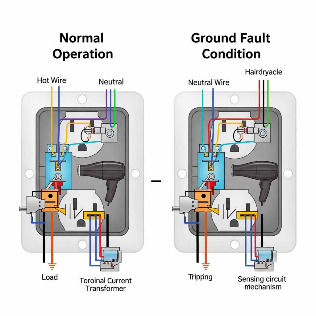
What Is a GFCI Outlet and How Does It Work?
A GFCI receptacle monitors current flow, comparing the hot wire’s outgoing current to the neutral wire’s return. In a balanced circuit, currents are equal. A ground fault (e.g., current leaking through a person) causes a current imbalance that a Class A GFCI is designed to detect (about 6 mA); the device trips within milliseconds to interrupt the circuit and limit the risk of shock (NEC 210.8). The NEC mandates GFCIs in wet/damp areas like bathrooms, kitchens, garages, and outdoors (NEC 210.8(A)–(B)).
Mastering GFCI Installation for Safety and Compliance
Following NFPA 70 (the NEC) and NFPA 70E, electricians ensure safe GFCI installations that protect users and meet code standards. Proper techniques prevent hazards and ensure reliability.
Installation and Safety Procedures
Step 1: De-Energize the Circuit
De-energize the circuit at the breaker panel and verify with a non-contact voltage tester or meter in accordance with NFPA 70E testing practice. Follow NFPA 70E lockout/tagout procedures to prevent accidental re-energization. Refer to NEC ampacity tables (for example Table 310.16) and NEC 310.15 for adjustment factors when more than three current-carrying conductors are grouped together.

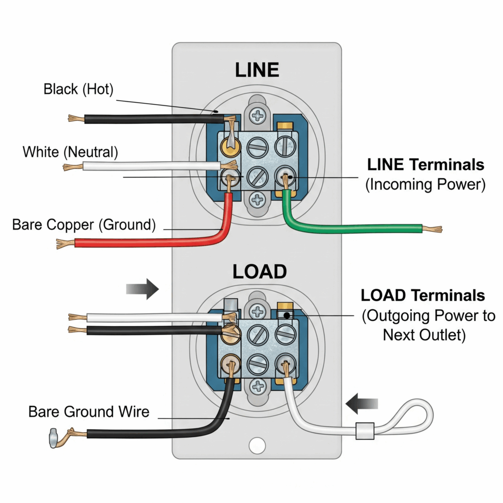
Step 2: Wire the GFCI
Identify LINE (incoming power) and LOAD (downstream outlets) terminals:
Attach the bare/green ground wire to the green grounding screw.
Incorrect LINE/LOAD connections disable GFCI functionality. For downstream protection, wire additional outlets to the LOAD terminals. Example: In a bathroom, a single GFCI receptacle can be wired to protect multiple downstream receptacles (NEC 210.8(A)).
Connect the black hot wire to the brass LINE terminal.
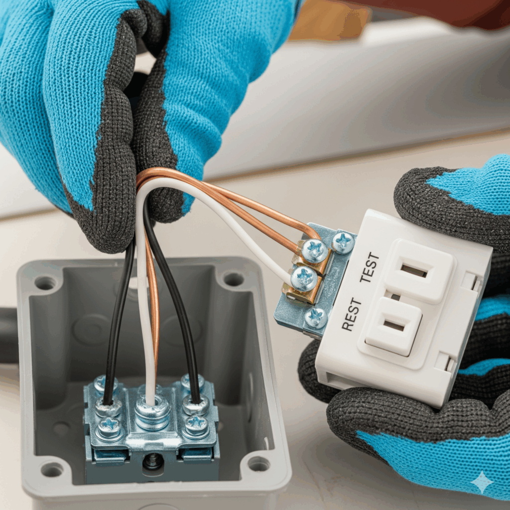
Step 3: Secure the Receptacle
Fold wires neatly, avoiding strain or pinching, and secure the GFCI into the electrical box (NEC 314.16 for box fill). Ensure clearances allow access per NEC’s definition of accessible (Article 100). Use appropriate cable-management methods and secure wiring without over-tightening; protect conductors from physical damage as required by NEC 300.4.
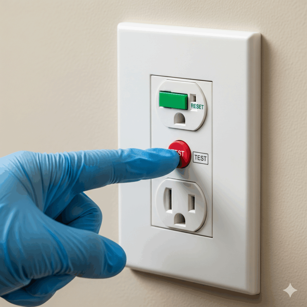
Step 4: Power and Test
Restore power, press the GFCI’s “RESET” button (the device should indicate it is energized), then press the “TEST” button to trip the device and confirm that power is interrupted to the receptacle and any downstream devices. Repeat to ensure reliable operation.
Safety Protocols
- PPE: Wear appropriate electrical PPE (insulating gloves, eye protection, and arc-rated clothing as required by NFPA 70E) when exposure to energized equipment or arc-flash hazards is possible.
- Verification: Always test circuits with a properly rated voltage tester or meter before beginning work, in accordance with NFPA 70E testing practices.
- Surge Protection: Install surge protective devices (SPDs) to safeguard connected equipment from transient voltage spikes; SPDs are not a substitute for required GFCI protection (NEC 285).
- Cable Management: Use appropriate cable ties or Velcro straps that are suitable for the environment (UV-resistant where exposed to sunlight) and secure wiring so it is protected from physical damage per NEC 300.4.
Conclusion
Installing ground fault circuit interrupter outlets requires precision, adherence to NFPA 70 (NEC 210.8, 314.16) and NFPA 70E, and rigorous safety practices. By de-energizing circuits, wiring correctly, testing thoroughly, and organizing cables, electricians ensure safe, compliant installations that protect users from electrical hazards.
Take the next step in your professional growth! Visit Expert CE (https://expertce.com/) for all your continuing education needs.
Continuing Education by State
Select your state to view board-approved continuing education courses and requirements:
Disclaimer: The information provided in this educational content has been prepared with care to reflect current regulatory requirements for continuing education. However, licensing rules and regulations can vary by state and are subject to change. While we strive for accuracy, ExpertCE cannot guarantee that all details are complete or up to date at the time of reading. For the most current and authoritative information, always refer directly to your state’s official licensing board or regulatory agency.
NEC®, NFPA 70E®, NFPA 70®, and National Electrical Code® are registered trademarks of the National Fire Protection Association® (NFPA®)
You may also like

Colorado Electrical Licensing Requirements and Reciprocity Guide

Standby Generators in DE: Navigating Coastal Storm Regulations
