Ground-Mount Solar Racking: Installation & Foundation Guide
Ground-Mount Solar Racking: Installation & Foundation Guide
Ground-mount solar racking systems offer a versatile and powerful alternative to rooftop installations, allowing for optimal panel orientation and scalability on open land. A successful installation hinges on three core pillars: a robust foundation engineered for site-specific conditions, strict adherence to NEC Article 690 for electrical safety, and a design that maximizes energy production. Key considerations include selecting the right solar foundation options—such as driven piles, helical piles, or ballasted systems—based on a thorough soil composition analysis. Proper grounding and bonding are critical for safety, requiring a compliant grounding electrode system and ensuring electrical continuity throughout all metal components. Additionally, precise wind load calculations are mandatory to guarantee structural integrity, while factors like system type, whether a fixed-tilt ground mount or single-axis tracker, will influence overall energy yield and project cost. For any journeyman electrician, mastering these elements is essential for expanding into the growing utility and large-scale residential solar market.
Understanding Ground-Mount Solar Racking Fundamentals
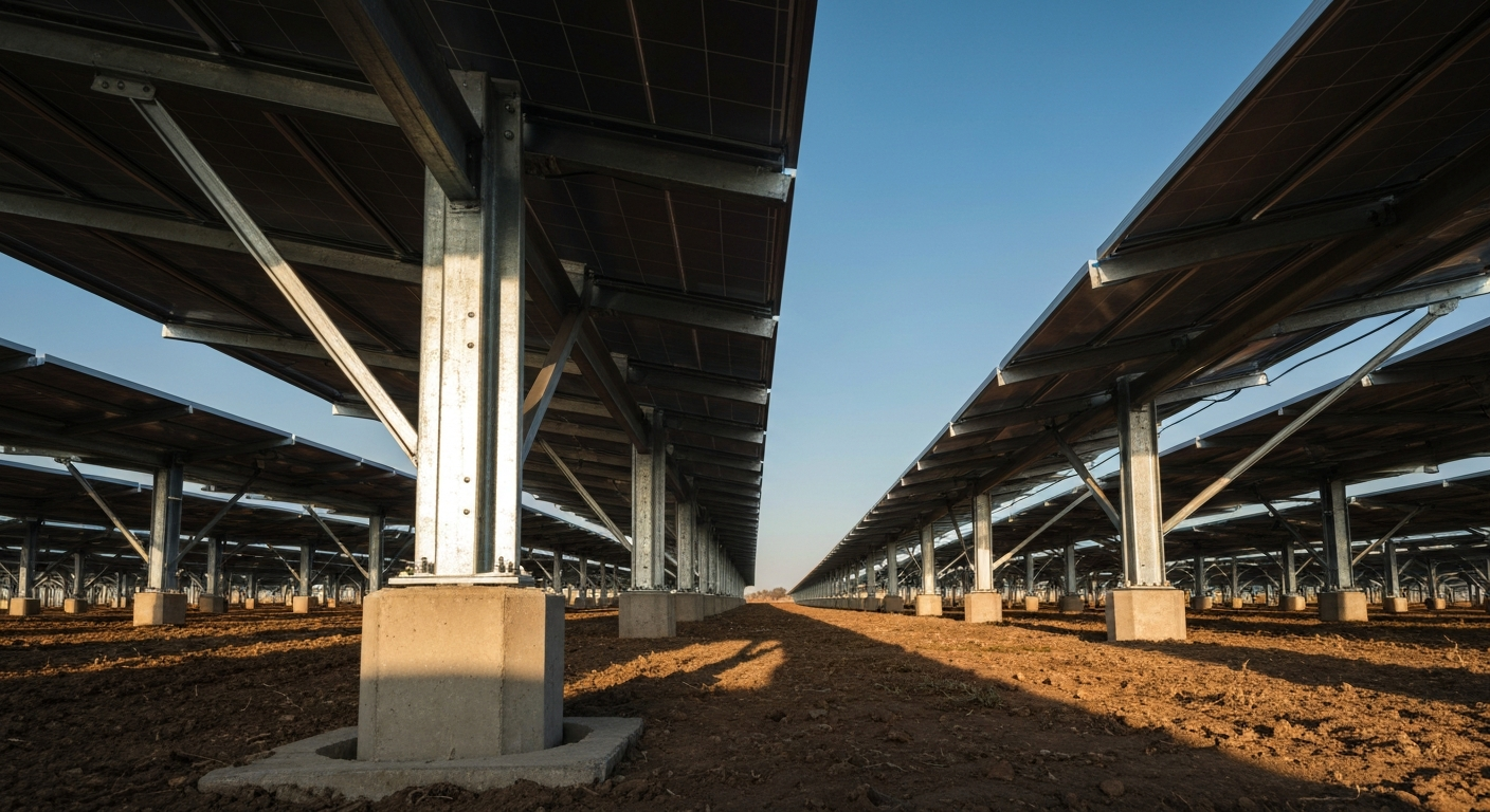
While rooftop arrays are common, ground-mount solar racking provides distinct advantages, particularly for large-scale projects or properties with unsuitable roofs. These systems use a metal framework anchored to the ground to support rows of solar panels. The primary benefits include the ability to orient the array for maximum solar exposure, easier access for maintenance, and improved airflow for better panel efficiency. Two main system types dominate the market:
- Fixed-Tilt Ground Mount: This is the simpler and more common design, where panels are set at a static, predetermined angle. The angle is optimized based on the site’s latitude to maximize annual energy production. Their robust, simple construction with no moving parts makes them highly reliable and cost-effective upfront.
- Single-Axis Trackers: These more advanced systems follow the sun’s path from east to west throughout the day. By continuously adjusting the panel angle, single-axis trackers can increase annual energy generation by 15-25% compared to fixed-tilt systems, creating a broader production curve that is often more valuable. The safety and function of these systems are evaluated under standards like UL 3703.
Site Assessment and Foundation: The Critical First Steps
The long-term stability and safety of a ground-mounted array depend entirely on the pre-installation groundwork. Rushing this phase can lead to structural failure, equipment damage, and significant safety hazards. A professional assessment must be performed by qualified personnel before any hardware is ordered.
Soil Composition Analysis and Its Impact
Before selecting a foundation, a thorough soil composition analysis is required. Geotechnical surveys determine the soil’s type, density, and load-bearing capacity. Is the ground composed of loose sand, dense clay, or solid rock? The answer dictates which foundation is feasible. For instance, weak or compressible soils may not support traditional driven piles, making alternatives like helical piles or ballasted systems necessary. This analysis is non-negotiable for ensuring the foundation can resist uplift and downward forces over decades of exposure.
Essential Wind Load Calculations
Ground-mounted arrays act like sails, catching significant wind. Therefore, accurate wind load calculations are a critical part of the structural design, as specified by standards like ASCE 7. These calculations determine the maximum uplift and shear forces the racking system will endure based on local wind speed data, exposure category, and the array’s tilt angle. The foundation and racking must be engineered to withstand these worst-case scenario forces to prevent catastrophic failure during a storm.
Choosing the Right Solar Foundation Options
With site data in hand, an engineer can specify the appropriate foundation. The most common solar foundation options include:
- Driven Pile Foundations: These are typically I-beams or C-channel posts driven directly into the ground with hydraulic hammers. They are cost-effective and fast to install in suitable soils but may be unworkable in rocky or very soft ground.
- Helical Piles: Also known as screw piles, these are large steel screws drilled into the earth. Helical piles offer excellent stability in a variety of challenging soils, including loose or wet conditions, and cause minimal ground disturbance.
- Ballasted Solar Racking: This non-penetrating option uses heavy concrete blocks or trays filled with aggregate to anchor the array. Ballasted solar racking is ideal for sites where excavation is not possible, such as landfills or properties with sensitive underground utilities.
- Concrete Piers: A traditional method involving poured-in-place concrete footings. While very strong, this method is more labor-intensive and requires significant curing time, making it less common for large-scale projects today.
NEC Compliance and Electrical Installation Best Practices
For any licensed electrician, all work must be grounded in the latest edition of the nec code book. NEC Article 690 is the definitive guide for solar photovoltaic (PV) systems, covering everything from conductor sizing to safety disconnects and grounding.
Grounding and Bonding: Ensuring System Safety
Often confused, grounding and bonding are two distinct but equally critical safety functions. Grounding connects the system to the earth to protect against lightning and high-voltage events, while bonding connects all metallic components to ensure they are at the same electrical potential. In practice, what is bonding? It’s the act of creating a continuous, low-impedance path to ensure fault current can safely trip a protective device like a circuit breaker. A complete grounding electrode system is mandatory for the structure supporting the PV system, and NEC Article 690 requires a documented grounding connection for PV systems attached to buildings. This often involves installing a dedicated grounding rod, a process detailed in our guide on how to properly install a ground rod per NEC requirements. Furthermore, proper equipment bonding of every rack, module frame, and enclosure is required to achieve electrical continuity. Modern racking systems listed to UL 2703 often have built-in bonding features, such as self-bonding clamps and splices, that simplify this process while helping to guarantee compliance.
Conductor Management and Protection
Proper conductor management is essential for the 25+ year lifespan of a solar array. All wiring must be protected from physical damage, moisture, and UV degradation. Conductors must be sized appropriately using a wire ampacity chart and corrected for ambient temperature conditions as specified in the NEC (Article 310 and the ampacity tables). Exposed single-conductor cables in PV arrays must be supported at intervals consistent with the PV wiring rules; for example, many exposed single-conductor PV cables have a 600 mm (24 in.) support interval identified in NEC 690.31 for smaller sizes. Wires should be routed through designated channels or secured with UV-resistant clips and ties listed for outdoor use. Using a properly listed conduit for runs between the array and the inverter provides robust protection, and all connections must be made within a properly rated outdoor electrical box.
Step-by-Step Guide to Voltage Drop Calculation
Minimizing voltage drop is crucial for maximizing system performance. Industry best practices suggest keeping voltage drop below 3% for PV circuits to ensure efficiency. Using a voltage drop calculator is the fastest method, but every professional should understand the manual calculation.
- Identify Key Variables: You need the one-way length of the conductor run (L) in feet, the maximum current (I) in amps (use Imp from the module datasheet), and the conductor resistance (R) in ohms per 1,000 feet (found in NEC Chapter 9, Table 8 or the conductor manufacturer’s datasheet).
- Apply the Formula: The formula for DC voltage drop is: Voltage Drop (V) = (2 x L x R x I) / 1000. The “2” accounts for the round-trip path of the DC circuit.
- Calculate an Example: For a 200-foot one-way run conducting 10 A: use the resistance for the exact conductor and temperature rating from NEC Chapter 9/Table 8 or the manufacturer. As an illustrative example only, if a resistance of 1.00 ohm per 1,000 ft is used for the chosen conductor at the operating temperature, then: V_drop = (2 × 200 × 1.00 × 10) / 1000 = 4.0 volts. This is only an example — always use the precise resistance value from the authoritative table for final design.
- Determine Percentage Drop: Divide the calculated voltage drop by the system’s maximum power voltage (Vmp). If Vmp is 300 V, the percentage drop is (4.0 V / 300 V) × 100 = 1.33%. This is within a 3% guideline. Always verify conductor R values in NEC Chapter 9 or the manufacturer’s data and confirm conductor ampacity/temperature ratings before finalizing conductor sizes.
Key Considerations for a Successful Installation
Beyond the core engineering and electrical work, several factors contribute to a high-quality, durable installation. Paying attention to these details demonstrates expertise and ensures long-term system health.
- UL 2703 Certification: Always use racking systems and components that are listed under UL 2703. This standard certifies that the mounting system has been tested for mechanical strength and for its ability to provide reliable equipment bonding.
- Proper Conductor Management: Avoid leaving wires resting on abrasive surfaces or exposed directly to the elements. Use listed wire clips and UV-rated ties to secure cables within racking channels, preventing insulation abrasion that can lead to ground faults.
- Accessibility and Maintenance: Design the array layout with sufficient space between rows for maintenance activities like cleaning panels or servicing equipment. Ground-level access makes these tasks significantly easier and safer compared to rooftop arrays.
- Career Opportunities: As the solar industry expands, the demand for qualified installers is growing. For a journeyman electrician, developing expertise in ground-mount systems opens up significant career opportunities, especially in the commercial and utility-scale sectors. To learn more, explore the landscape of solar career opportunities for electricians.
The ground-mount solar sector is rapidly advancing with innovative racking and foundation technologies. Expand your services with ground-mount systems. Learn more in our courses.
Primary Sources
- National Fire Protection Association (NFPA) for the National Electrical Code (NEC)
Frequently Asked Questions (FAQ)
- What are the main types of ground-mount solar racking foundations?
- The primary solar foundation options include driven piles (steel posts hammered into the ground), helical piles (large screws drilled into the soil), concrete piers (poured footings), and ballasted systems that use heavy weights instead of ground penetration. The best choice depends on soil conditions, wind loads, and project budget.
- How does NEC Article 690 apply to grounding and bonding in a ground-mount solar installation?
- NEC Article 690 mandates that all exposed non-current-carrying metal parts, including module frames and racking, must be bonded together to create an effective ground-fault current path. The entire system must also be connected to a grounding electrode system (e.g., a ground rod) to protect against overvoltage events like lightning, and NEC Article 690 includes requirements and marking provisions to support that. UL 2703-listed racking is commonly used to simplify meeting these equipment bonding requirements.
- Is a single-axis tracker better than a fixed-tilt ground mount system?
- A single-axis tracker can increase energy production by up to 25% over a fixed-tilt ground mount system by following the sun. However, trackers are more expensive, have moving parts that require maintenance, and are more complex to install. The decision depends on a project’s financial goals, available land, and tolerance for higher operational expenses.
- What is UL 2703 and why is it important for ground-mount solar racking?
- UL 2703 is a safety standard for PV mounting and racking systems. It evaluates the mechanical strength of the racking and, crucially, certifies its integrated bonding and grounding capabilities. Using a UL 2703-listed ground-mount solar racking system helps ensure module frames are reliably bonded to the rack, simplifying installation and helping to meet NEC requirements for electrical continuity.
Continuing Education by State
Select your state to view board-approved continuing education courses and requirements:
Disclaimer: The information provided in this educational content has been prepared with care to reflect current regulatory requirements for continuing education. However, licensing rules and regulations can vary by state and are subject to change. While we strive for accuracy, ExpertCE cannot guarantee that all details are complete or up to date at the time of reading. For the most current and authoritative information, always refer directly to your state’s official licensing board or regulatory agency.
NEC®, NFPA 70E®, NFPA 70®, and National Electrical Code® are registered trademarks of the National Fire Protection Association® (NFPA®)
You may also like

Colorado Electrical Licensing Requirements and Reciprocity Guide

Standby Generators in DE: Navigating Coastal Storm Regulations
