Gears and Ratios Explained: A Mechanical Aptitude Study Guide
Why Gears and Ratios Matter for Electricians
While an electrician’s primary focus is on circuits, conductors, and the NEC code book, the power from an electric motor must be translated into useful work. This is where mechanical systems like gears take over. For a journeyman electrician or a specialized maintenance electrician, understanding this handoff between the electrical and mechanical worlds is non-negotiable.
Many industrial roles involve troubleshooting entire systems, not just the wiring. If a conveyor belt isn’t moving at the right speed or a motorized lift can’t handle its rated load, the problem might not be the motor’s voltage but the gearbox it’s connected to. Knowing how gear ratios affect performance allows you to diagnose problems more effectively. This expertise is a significant component of advanced electrician training and is often a topic covered in curriculums from bodies like NCCER. Furthermore, mechanical aptitude is often a prerequisite for positions in industrial plants, where you’ll be responsible for the upkeep of everything from pumps and fans to complex automated machinery.
The Fundamentals: Driver and Driven Gears
Understanding the Core Concepts: Torque and Speed
The relationship between torque and speed is the most critical concept in gearing. It’s an inverse relationship: when you use gears to increase torque, you decrease speed, and when you increase speed, you decrease torque.
- Torque: This is the rotational or “twisting” force. A high-torque setup can move heavy loads but will do so slowly. Think of it as strength.
- Speed: Measured in revolutions per minute (RPM), this is how fast the output shaft is turning.
Power from electrical motors is transmitted through a driver gear (the input gear connected to the motor) to a driven gear (the output gear connected to the load). By changing the size of these gears relative to each other, you can tailor the motor’s output to the specific needs of the application, a concept known as achieving mechanical advantage.
How to Perform a Gear Ratio Calculation
The gear ratio calculation is straightforward and relies on the number of teeth on each gear. It tells you how many times the driver gear must turn to make the driven gear complete one full rotation.
- Identify the Driver and Driven Gears: The driver gear is connected to the power source (the motor), while the driven gear is connected to the output shaft.
- Count the Teeth on Each Gear: Accurately count the number of teeth on both the driver gear (T1) and the driven gear (T2).
- Apply the Formula: The gear ratio formula is: Gear Ratio = Number of Teeth on Driven Gear (T2) / Number of Teeth on Driver Gear (T1).
- Interpret the Result:
- If the ratio is greater than 1 (e.g., 4:1), it’s a speed reduction. The output is slower but has more torque. The driver gear must turn four times to make the driven gear turn once.
- If the ratio is less than 1 (e.g., 0.25:1 or 1:4), it’s a speed increase. The output is faster but has less torque. The driver gear turns once to make the driven gear turn four times.
The Gear Train: Simple, Compound, and Idler Gears
A gear train is simply two or more gears working together. Different arrangements are used to achieve specific outcomes in power transmission.
Simple Gear Trains and Rotational Direction
In the simplest arrangement, two gears mesh directly. An important rule to remember for your mechanical aptitude test is that when two external gears mesh, they always turn in opposite directions. This change in rotational direction is a fundamental property of a simple gear train.
The Role of the Idler Gear
What if you need the output shaft to rotate in the same direction as the input, but don’t want to use a belt? You would use an idler gear. An idler gear is placed between the driver and driven gears. It reverses the direction of rotation of the gear it meshes with. By adding this third gear, the final driven gear will now rotate in the same direction as the driver gear. An idler gear does not change the overall gear ratio; its sole purposes are to change the direction of rotation or to bridge a gap between two distant gears.
Understanding Compound Gears for Mechanical Advantage
To achieve a large gear ratio in a compact space, engineers use compound gears. A compound gear is when two gears of different sizes are fixed to the same shaft, so they rotate at the same speed. By creating a gear train with compound gears, you can multiply the ratios. For example, the ratio of the first pair is multiplied by the ratio of the second pair, allowing for very large increases in torque (or speed) without needing one giant gear.
Practical Applications in the Electrical Trade
This knowledge moves from theoretical to practical when you’re on the job site. A master electrician overseeing an industrial installation or a service technician troubleshooting a fault needs to see the whole picture.
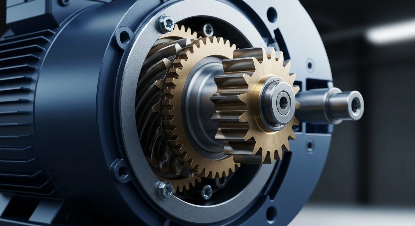
Gears in Electrical Motors and Power Transmission
Gears are essential companions to electrical motors. A motor might spin at 1,800 RPM, but the application may require a slow, powerful rotation. A gearbox is used to make this conversion. Understanding this relationship is also key when working with modern motor controls. For example, while gears provide a fixed mechanical speed reduction, a variable frequency drive (VFD) can electronically adjust the motor’s speed. Often, these two systems work together—the gearbox sets the fundamental torque/speed range, and the VFD provides fine-tuned control within that range.
Pulleys and Belts: A Close Cousin to Gears
Similar to gears, pulleys and belts are used to transmit power, often over longer distances where meshing gears would be impractical. The ratio is calculated based on the diameters of the pulleys instead of the number of teeth. Unlike gears, which provide a positive drive without slippage, belt systems can slip under heavy load, which can sometimes be a protective feature.
A solid foundation in these mechanical principles is a hallmark of a top-tier electrician. It sets you apart and is essential for passing a tough journeyman electrician exam. Don’t let mechanical concepts slow you down. Sign up for our exam prep.
Preparing for Your Mechanical Aptitude Test
For those attending an electrician school or pursuing online electrical courses, dedicating study time to mechanical principles is crucial. These topics are frequently a major part of pre-employment screening and licensing exams.
- Focus on Relationships: Don’t just memorize formulas. Understand the inverse relationship between speed and torque and how gear size affects it.
- Practice Calculations: Work through dozens of gear ratio calculation problems with simple, compound, and idler gear setups.
- Visualize Direction: Draw out gear trains and trace the rotational direction of each gear. Remember that an odd number of gears results in the first and last gear turning the same way.
- Connect to Electrical Controls: Think about how a device like a motor-rated switch is the control point for the entire mechanical system that follows. An electrician must ensure the control and protection are appropriate for both the motor and the mechanical load it serves.
Frequently Asked Questions (FAQ)
How do I perform a basic gear ratio calculation?
To perform a basic gear ratio calculation, you divide the number of teeth on the driven (output) gear by the number of teeth on the driver (input) gear. For example, if the driven gear has 60 teeth and the driver has 20, the ratio is 60/20, which simplifies to 3:1. This means the input must turn three times for the output to turn once.
What is the difference between torque and speed in a gear system?
Torque and speed have an inverse relationship. Torque is the rotational force or strength of the system, while speed is the rotational velocity (RPM). When you use gears to increase torque (e.g., using a small driver gear to turn a large driven gear), you decrease the output speed. Conversely, increasing speed reduces available torque.
Why is understanding gears important for a maintenance electrician?
A maintenance electrician is often responsible for the entire electromechanical system. Understanding gears is crucial for troubleshooting equipment like conveyors, pumps, and automated machinery where problems may stem from mechanical failure (like a stripped gear) rather than an electrical fault. This knowledge allows for faster and more accurate diagnostics.
Do online electrical courses cover mechanical concepts like gears?
Yes, many comprehensive online electrical courses and electrician school programs, especially those preparing students for the journeyman electrician exam or industrial roles, include modules on mechanical aptitude. These sections cover essential topics like gears, pulleys, and levers, as they are integral to understanding how electrical motors perform work.
Continuing Education by State
Select your state to view board-approved continuing education courses and requirements:
Disclaimer: The information provided in this educational content has been prepared with care to reflect current regulatory requirements for continuing education. However, licensing rules and regulations can vary by state and are subject to change. While we strive for accuracy, ExpertCE cannot guarantee that all details are complete or up to date at the time of reading. For the most current and authoritative information, always refer directly to your state’s official licensing board or regulatory agency.
NEC®, NFPA 70E®, NFPA 70®, and National Electrical Code® are registered trademarks of the National Fire Protection Association® (NFPA®)
You may also like

Colorado Electrical Licensing Requirements and Reciprocity Guide

Standby Generators in DE: Navigating Coastal Storm Regulations
