The Difference Between a Switch and a Relay: A Technical Primer
The Difference Between a Switch and a Relay: A Technical Primer
At a fundamental level, the debate of switch vs relay comes down to control. A switch is a manually operated device that directly opens or closes a circuit, like flipping a light switch on a wall. A relay, in contrast, is an electrically operated switch. It uses a small, separate low-voltage control circuit to manage a much larger, high-power load circuit. This core difference enables remote switching and automation, which is impossible with a simple mechanical switch. For instance, an electromagnetic coil in a relay, when energized by a low-power signal, creates a magnetic field that physically closes contacts to power a heavy-duty motor. This provides critical electrical isolation, protecting sensitive controls from the high-power load. While switches are perfect for direct user input, relays are indispensable for industrial automation, motor control, and safely handling high-power applications.
What is a Switch? The Foundation of Circuit Control
A switch is one of the most fundamental components in an electrical circuit. Its function is straightforward: to manually interrupt or complete a path for current to flow. When you physically actuate a switch—by flipping, pressing, or turning it—you are mechanically closing or opening the contacts within it. This direct action makes switches intuitive and reliable for on-the-spot control.
Every journeyman electrician and master electrician works with various types of switches daily. Common examples include the standard single-pole toggle for a room’s lighting, as well as more complex configurations for controlling a single fixture from multiple locations. Understanding these is crucial for residential and commercial wiring. For example, learning how to wire a 3-way switch or even a 4 way switch allows for sophisticated lighting control from several points in a large room or hallway. Switches are defined by their simplicity and direct mode of operation; the user is the direct agent of change for the circuit.
What is a Relay? Automated and Remote Switching
A relay is best understood as an automated, electrically operated switch. Unlike a manual switch, a relay doesn’t require a person to physically interact with it to change its state. Instead, it uses a separate, low-power electrical signal to control a completely different, often high-power, circuit. This separation is the key to a relay’s power and versatility.
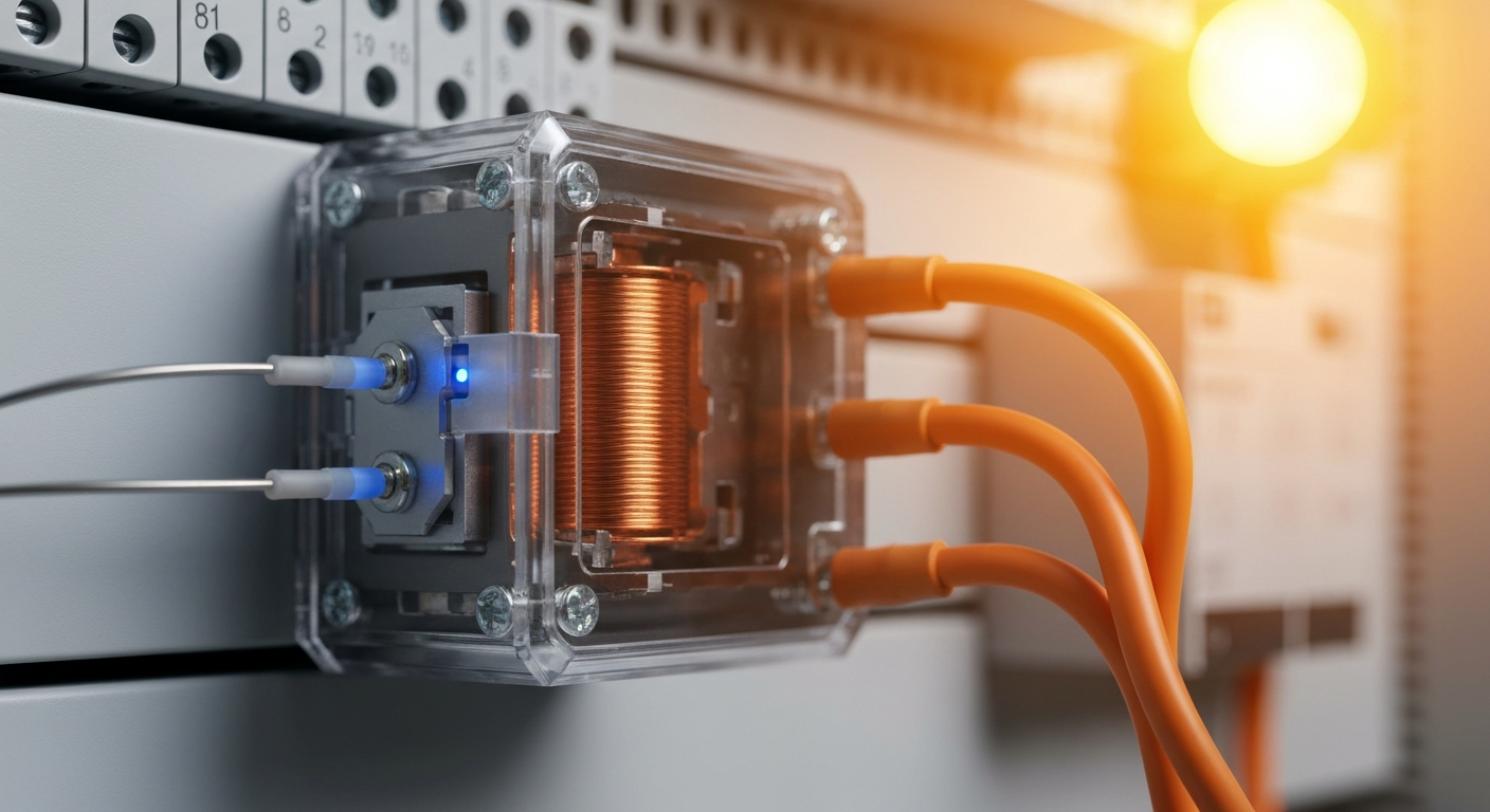
The classic electromechanical relay (EMR) works on a simple magnetic principle. It contains two distinct circuits: a control circuit and a load circuit.
- Control Circuit: This circuit contains an Electromagnetic coil that requires only a small amount of current (a low voltage signal) to activate.
- Load Circuit: This circuit is connected to the heavy load, such as a large motor or a bank of lights, and its contacts are physically moved by the action of the coil.
When the control circuit is energized, the coil becomes a magnet, which pulls an armature to close a set of contacts in the load circuit, allowing high current to flow to the device. The contacts in the load circuit are described by their default state: normally open (NO), where the circuit is off by default, or normally closed (NC), where the circuit is on by default. This ability to use a small signal for high-power switching is fundamental to modern electrical systems.
Switch vs Relay: The Core Differences Explained
While both components control current, their operational principles and applications are fundamentally different. For working electricians, knowing when to use one over the other is critical for safety, efficiency, and system design.
Control Method: Manual vs. Automated
The most significant distinction lies in how they are operated. A switch is a manual device. A relay is an automatic device, triggered by an electrical signal. This enables remote switching, allowing you to control equipment from a distance or automate it based on inputs from sensors, timers, or programmable logic controllers (PLCs). This is the foundation of all industrial automation.
Electrical Isolation: A Critical Safety Feature
A relay provides electrical isolation between the control and load circuits. This means the low-voltage side that operates the coil is completely separate from the high-voltage side that powers the load. This is a crucial safety feature, protecting sensitive electronic controls (like a microcontroller) from the powerful and potentially noisy electrical environment of a motor or compressor. A standard switch offers no such isolation.
Application and Power Handling
Switches are typically used for lower-power applications like residential lighting and small appliances. Relays, however, are designed to handle a wide range of currents—from small signal switching up to heavy industrial loads. General-purpose relays are commonly used for low- to moderate-current control, while contactors are purpose-built for much higher currents and are the standard choice for starting and switching large motors and other heavy industrial loads; contactor ratings span a broad range, from tens of amperes to thousands, depending on the application and manufacturer. Always select devices based on the motor or load nameplate and the application requirements.
Types of Relays: Electromechanical vs. Solid-State
The world of relays is broadly divided into two categories, each with its own strengths, reflecting a major trend in industrial technology.
Electromechanical Relay (EMR)
This is the traditional relay with a physical coil and moving contacts. They are robust, cost-effective, and can tolerate momentary voltage spikes. However, their mechanical parts can wear out over time, and they produce a small but audible “click” when activated.
Solid-State Relay (SSR)
A solid-state relay has no moving parts. Instead, it uses semiconductor devices like thyristors or transistors to switch the load. SSRs offer significant advantages: they are silent, have much faster switching speeds, and have a long operational life since there are no physical contacts to wear out. Be aware that SSRs have different thermal and transient characteristics than electromechanical relays, and some SSR designs may rely on semiconductor coupling and therefore differ in the level of galvanic isolation they provide—check manufacturer specifications for isolation and thermal management when replacing EMRs with SSRs.
Practical Applications and NEC Considerations
For a licensed electrician, these concepts directly apply to daily work, from residential wiring to complex industrial installations.
How a Relay Works: Step-by-Step
Understanding the sequence of operation for an EMR is key exam-prep knowledge:
- A low-voltage signal is applied to the control circuit’s input terminals, energizing the electromagnetic coil.
- The energized coil generates a magnetic field.
- This magnetic field attracts a movable armature.
- The armature’s movement forces the contacts in the load circuit to change state. A normally open contact will close, and a normally closed contact will open.
- Power now flows through the closed contacts to the high-power load (e.g., a motor or heater).
- When the control signal is removed, the magnetic field collapses, a spring returns the armature to its original position, and the load circuit is de-energized.
This process is central to applications like motor control, where a relay or contactor can be used for starting and stopping motors or for integration into protective control schemes. NEC Article 430 addresses motors, motor circuits, and controllers, and is the authoritative NEC reference for the requirements and limits governing motor control equipment and its protective devices. A specialized switch, known as a motor-rated switch, is also designed for high-inrush conditions but typically functions as a manual disconnect or control device rather than an automatic switching element.
Relays are also critical in systems like a transfer switch for generator setups, where they automatically switch a building’s power source from the utility grid to a backup generator during an outage. In HVAC systems, relays are used to control blowers and compressors, often triggered by a line voltage thermostat. The rules for installing these components—particularly wiring and overcurrent protection inside control panels—are covered by the NEC and related articles; Article 430 is central for motor control. Article 725 covers certain control-circuit classes and the conditions for power-limited circuits; follow the appropriate NEC articles and device listings when designing and installing control and power circuits.
Mastering these components is essential for advancing in the trade. Master control wiring and automation. Explore our advanced theory courses.
Key Takeaways: Switch vs. Relay
- Operation: Switches are manual; relays are electrically automated.
- Control: Switches provide direct control. Relays allow for remote and automated control.
- Isolation: Relays provide electrical isolation between the control and load circuits, a key safety feature. Switches do not.
- Power: Switches are common in lower-power circuits. Relays and contactors are built for high-power switching where required by the load.
- Common Circuits: Switches are used in fundamental circuits like residential lighting (e.g., series vs parallel circuit designs), while a motor control center uses relays/contactors and associated protective devices per NEC requirements.
- Types: Relays come in electromechanical (EMR) and solid-state relay (SSR) versions, with SSRs gaining popularity for many industrial uses; selection should account for thermal performance, isolation, and switching characteristics.
Primary Sources
- National Fire Protection Association (NFPA) for the National Electrical Code (NEC).
Frequently Asked Questions (FAQ)
When should I use a relay instead of a switch?
You should use a relay when you need to control a circuit automatically or remotely, when you need to switch a high-power load using a low-power signal, or when you require electrical isolation between the control circuit and the load circuit for safety. Common scenarios include motor control, industrial automation, and automotive electronics.
What is the difference between a relay and a contactor?
A contactor is essentially a heavier-duty switching device (a specialized type of relay) designed specifically for high-current industrial applications. Contactors are used for switching large motors, heavy lighting, and other high-current loads and are rated significantly higher than small signal relays. Exact ratings vary by manufacturer, so always pick the device rated for the motor nameplate and the intended application.
Can a solid-state relay (SSR) replace an electromechanical relay (EMR)?
In many cases, yes. A solid-state relay can replace an EMR, offering benefits like a much longer life, faster switching, and silent operation. However, SSRs behave differently electrically (heat dissipation, on-state voltage drop, and transient robustness) and in some cases may not provide the same galvanic isolation as an EMR—so check the manufacturer’s datasheet and the application’s requirements before replacing EMRs with SSRs.
Continuing Education by State
Select your state to view board-approved continuing education courses and requirements:
Disclaimer: The information provided in this educational content has been prepared with care to reflect current regulatory requirements for continuing education. However, licensing rules and regulations can vary by state and are subject to change. While we strive for accuracy, ExpertCE cannot guarantee that all details are complete or up to date at the time of reading. For the most current and authoritative information, always refer directly to your state’s official licensing board or regulatory agency.
NEC®, NFPA 70E®, NFPA 70®, and National Electrical Code® are registered trademarks of the National Fire Protection Association® (NFPA®)
You may also like

Colorado Electrical Licensing Requirements and Reciprocity Guide

Standby Generators in DE: Navigating Coastal Storm Regulations
