Coupling and Uncoupling Procedures for Tractor-Trailers
Mastering Tractor-Trailer Coupling and Uncoupling Procedures for Electrical Professionals
Proper coupling and uncoupling procedures are fundamental to the safety and efficiency of the entire trucking industry. While the mechanical locking of the fifth wheel is critical, the electrical connection is equally vital, powering everything from essential safety systems to complex onboard technology. For a journeyman electrician or master electrician working in fleet maintenance, a deep understanding of the tractor-trailer electrical interface is non-negotiable. This involves more than just plugging in a cable; it requires knowledge of the SAE J560 standard, proficiency in 7-pin trailer connector wiring, and the ability to perform swift trailer lighting circuit troubleshooting. As technology advances, the scope now includes everything from ABS power and diagnostics to powering telematics and high-voltage EV systems. This guide provides the expert insights needed to master these procedures, ensuring every connection is safe, compliant, and reliable. Sharpen your skills with our specialized online electrical courses to stay ahead in your field.
The Critical Role of the Electrical Interface in Coupling
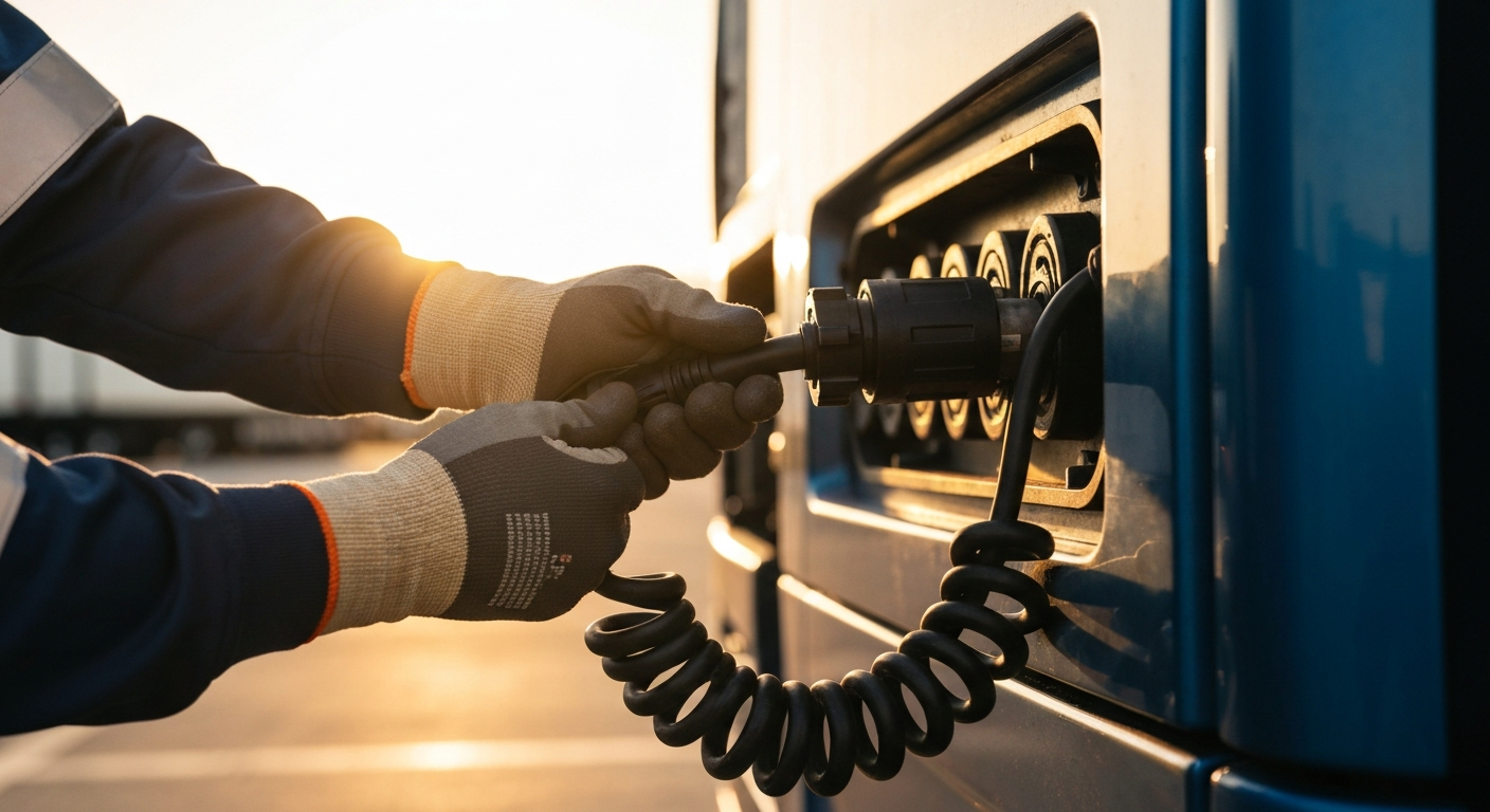
For the modern electrician, a tractor-trailer is a complex mobile network. The electrical connection, commonly known as the pigtail, is the lifeline that integrates the tractor’s power and control systems with the trailer. This single connection is responsible for legally mandated lighting, anti-lock brakes (ABS), and increasingly, a host of auxiliary systems. A failure here is not a minor inconvenience; it can lead to catastrophic accidents, costly downtime, and significant legal liability. Therefore, a core component of any comprehensive electrician training for fleet maintenance is a focus on this crucial interface.
The industry benchmark for this connection in North America is the SAE J560 standard. This specification standardizes the physical and electrical characteristics of the 7-pin connector, ensuring interoperability between different makes of tractors and trailers. It governs the pinout, wire colors, and circuit functions, providing a universal language for diagnostics and repair.
A Step-by-Step Guide to Electrical Coupling Procedures
A systematic approach is essential for ensuring a perfect electrical connection every time. Rushing this process can lead to intermittent faults that are difficult to diagnose later.
- Pre-Connection Inspection: Before making the connection, visually inspect both the tractor’s pigtail and the trailer’s receptacle. Look for signs of corrosion, bent pins, or frayed wiring. If damage is found, a tractor pigtail connector repair may be necessary before proceeding. Check for a clean and secure trailer electrical grounding pin, as a poor ground is the root cause of many electrical issues.
- Understand the Pinout: Familiarize yourself with the 7-pin trailer connector wiring configuration per the SAE J560 standard. Common color conventions you will encounter include ground (white), tail/marker/clearance lamps (brown), left turn/stop (yellow on many trailers where circuits are combined), stop/brake (red on some applications), right turn (green), and auxiliary/ABS (blue). Color conventions and whether stop and turn are combined or separate can vary by vehicle and equipment, so always verify pin functions against SAE J560 and the specific vehicle wiring diagram. This knowledge is crucial for effective trailer lighting circuit troubleshooting.
- Make a Secure Physical Connection: Align the connector properly and push it firmly into the receptacle. Ensure the locking tab on the receptacle’s cover engages securely with the connector to prevent it from vibrating loose on the road. A loose connection can cause arcing and damage to the pins.
- Perform a Full Systems Check: Once connected, power up the tractor and systematically check all trailer functions from the cab. This includes all lights (running lights, turn signals, brake lights, hazards) and, critically, the ABS wiring and module. A proper ABS power and diagnostics check typically involves verifying power and signal continuity to the trailer ABS module and observing its self-test behavior; the ABS malfunction lamp may illuminate briefly during a self-test on some tractors, but the exact indication varies by manufacturer, so consult the OEM documentation.
- Verify Auxiliary and Specialized Systems: For trailers with additional equipment, perform secondary checks. This includes systems for liftgate electrical maintenance, telematics, and lighting on specialized trailers. For reefer unit power systems, the refrigeration compressor is commonly powered by the unit’s onboard diesel genset or by external shore power; the tractor’s SAE J560 connection provides 12 V for lighting and low-voltage controls, but high-power refrigeration loads are supplied by the reefer’s own power source or an external high-power connection where provided.
Advanced Electrical Systems and Modern Challenges
The tractor-trailer electrical landscape is rapidly evolving beyond the traditional 7-pin connector. Electricians must stay current with emerging technologies to remain effective.
Powering Onboard Technology and High-Voltage Systems
Modern fleets rely heavily on data. Powering trailer telematics systems for tracking, diagnostics, and remote monitoring often runs through the main electrical interface or dedicated circuits. Furthermore, the advent of EV truck high-voltage coupling introduces an entirely new level of complexity and safety protocols. These systems do not use the SAE J560 connector for high-voltage power transfer. Instead, emerging standards like the Megawatt Charging System (MCS), also known as SAE J3271, utilize separate, dedicated high-voltage connectors designed for rapid, high-power charging. This demands specialized training far beyond standard low-voltage systems. While SAE J560 remains dominant for North American conventional systems, be aware that international or specialized equipment may follow different ISO or regional standards for trailer connections.
Troubleshooting Common Electrical Interface Issues
Effective trailer electrical diagnostics is a highly valuable skill. When a driver reports an issue, the electrician’s job is to identify the fault efficiently. This often starts with the pigtail and connector. Common problems include water intrusion, corrosion, and broken wires from repeated flexing. Using a multimeter to check for continuity and voltage at the connector is a basic first step. For more complex issues like intermittent voltage drops, using a voltage drop calculator can help determine if the wiring gauge is sufficient for the load, especially on long trailers. When adding or modifying circuits, always consult an ampacity chart and the vehicle or equipment manufacturer’s guidance to ensure wiring is not overloaded; authoritative vehicle wiring standards (for example, SAE wiring documents) and OEM instructions should be followed.
Key Components in Trailer Electrical Safety
- Trailer Breakaway Switch: This is a critical safety system that differs based on brake type. On many lighter-duty trailers with electric brakes, a physical trailer breakaway switch wiring pulls a pin to activate an onboard battery and apply the trailer’s electric brakes if it detaches. However, heavy-duty tractor-trailers use air brakes. Their emergency response to a loss of air (for example, from separation of the emergency air line, the red gladhand) results in the trailer’s spring brakes being applied automatically.
- Grounding: As mentioned, proper trailer electrical grounding is paramount. The ground wire provides the return path for all circuits. A faulty or corroded ground connection forces current to find alternative paths, often leading to flickering lights, incorrect ABS behavior, and phantom electrical faults.
- Circuit Protection: Ensure all circuits, especially high-draw auxiliary trailer power circuits, are properly protected per the vehicle manufacturer and applicable standards (fuses or circuit breakers sized per wiring ampacity and device requirements). This prevents electrical overloads from damaging the trailer’s wiring or components.
To master the electrical aspects of truck and trailer maintenance, continuous learning is essential. Ensure a secure connection. Learn the correct coupling procedures. Staying updated on standards and new technologies will not only make you a better technician but also enhance the safety and reliability of the vehicles you service.
Frequently Asked Questions (FAQ)
What is the SAE J560 standard and why is it important for coupling and uncoupling procedures?
The SAE J560 standard is a specification from SAE International that defines the standardized 7-pin connector used for the tractor-trailer electrical interface in North America. Its importance lies in ensuring electrical compatibility between any tractor and trailer, regardless of the manufacturer. It dictates the pinout, circuit functions, and physical dimensions, which is critical for safe and reliable power for lights, brakes (ABS), and other essential systems during coupling and uncoupling procedures. Because color conventions and some circuit combinations can vary, technicians should always confirm pin functions against the SAE J560 documentation and the specific vehicle wiring diagrams.
How do I perform trailer lighting circuit troubleshooting?
Trailer lighting circuit troubleshooting typically starts at the 7-pin connector. First, perform a visual inspection of the pigtail and receptacle. Next, use a circuit tester or multimeter to verify power is being sent from the tractor for the specific malfunctioning circuit (e.g., left turn signal). If the tractor is sending power, the issue lies in the trailer’s wiring. Check the bulb, socket, and trace the wire back from the light, paying close attention to the ground connection, as a bad ground is a common culprit.
What is the main difference in wiring for Reefer unit power systems versus standard lights?
Standard trailer lighting and ABS run on 12V DC power supplied through the primary 7-pin trailer connector wiring or other low-voltage circuits and are relatively low-amperage. In contrast, reefer unit power systems for refrigeration compressors are typically supplied by the reefer’s onboard diesel genset or by external shore/high-power connections. The tractor’s SAE J560 connection provides 12 V for the reefer’s running lights and low-voltage controls, but it does not supply the high-power compressor load.
As a journeyman electrician, what are the key skills for trailer electrical diagnostics?
For a journeyman electrician, key skills in trailer electrical diagnostics include a thorough understanding of the SAE J560 standard and vehicle wiring practices, proficiency with a multimeter to test voltage and continuity, and the ability to read wiring diagrams. You should be able to diagnose issues related to poor grounding, voltage drop, and short circuits. Knowledge of ABS power and diagnostics is also essential, as is understanding how to safely troubleshoot auxiliary circuits for liftgates or telematics systems.
Continuing Education by State
Select your state to view board-approved continuing education courses and requirements:
Disclaimer: The information provided in this educational content has been prepared with care to reflect current regulatory requirements for continuing education. However, licensing rules and regulations can vary by state and are subject to change. While we strive for accuracy, ExpertCE cannot guarantee that all details are complete or up to date at the time of reading. For the most current and authoritative information, always refer directly to your state’s official licensing board or regulatory agency.
NEC®, NFPA 70E®, NFPA 70®, and National Electrical Code® are registered trademarks of the National Fire Protection Association® (NFPA®)
You may also like

Colorado Electrical Licensing Requirements and Reciprocity Guide

Standby Generators in DE: Navigating Coastal Storm Regulations
