Sizing PV Conductors & OCPD per NEC Article 690
The Critical Role of Accurate Conductor Sizing in Solar Installations
For any Journeyman Electrician or Master Electrician, designing and installing a photovoltaic (PV) system demands a meticulous approach to electrical safety and performance. At the heart of this process is the correct sizing of conductors and overcurrent protective devices (OCPDs). Unlike standard electrical circuits, PV systems have unique characteristics that are addressed in Article 690 of the National Electrical Code (NEC), which is the primary section of the NFPA 70 standard dealing with solar installations. As solar modules become more powerful, miscalculations can lead to significant energy loss, system failure, or catastrophic fire events. Understanding the nuances of the NEC 2023 solar code is essential for compliance and safety.
Foundational Concepts: Voltage, Current, and PV String Sizing
Before diving into calculations, it’s crucial to understand how PV arrays are configured and the key electrical data you’ll need from the module’s datasheet.
Series vs Parallel Circuit Connections
PV string sizing begins with understanding basic circuit principles. Connecting modules in a series vs parallel circuit has distinct effects:
- Series Connection: When modules are connected in series (positive to negative), their voltages add up, while the current (amperage) remains the same as a single module. This is done to achieve the necessary voltage window for the inverter to operate efficiently.
- Parallel Connection: When strings of modules are connected in parallel (positives together and negatives together), their currents add up, while the voltage remains the same as a single string. This is used to increase the total power output of the array.
Key Datasheet Values for NEC Calculations
Every calculation starts with the PV module’s datasheet. You must identify:
- Open-Circuit Voltage (Voc): The maximum voltage a module can produce with no load connected. This value is critical for calculating maximum PV system voltage.
- Short-Circuit Current (Isc): The maximum current a module can produce during a short-circuit condition. This is the starting point for all ampacity and OCPD for PV systems calculations.
- Temperature Coefficient of Voc: This specifies how much the voltage changes for every degree of temperature change from the Standard Test Condition (STC) of 25°C.
Calculating Maximum PV System Voltage per NEC 690.7
One of the first and most critical safety calculations is determining the maximum system voltage. PV module voltage increases as the temperature drops. NEC 690.7 requires you to calculate the corrected voltage for the coldest expected temperature at the site to ensure you do not exceed the voltage rating of the inverter or other DC components.
To do this, you must use either the temperature coefficients provided by the module manufacturer (the more precise method) or the correction factors from NEC Table 690.7(A). The formula using the coefficient is:
Corrected Voc = Voc x [1 + (Lowest Temp °C – 25°C) x (Temp. Coefficient of Voc %/°C)]
Multiplying this corrected single-module Voc by the number of modules in your longest series string gives you the maximum system voltage. This value must not exceed the inverter’s maximum DC input voltage rating or the system voltage limitation (e.g., 600V for one- and two-family dwellings).
A Step-by-Step Guide to NEC 690.8 Conductor Sizing
NEC 690 conductor sizing for PV source and output circuits is a multi-step process that accounts for increased irradiance (“edge of cloud” effect) and continuous load factors. These are the core NEC 690.8 calculations.
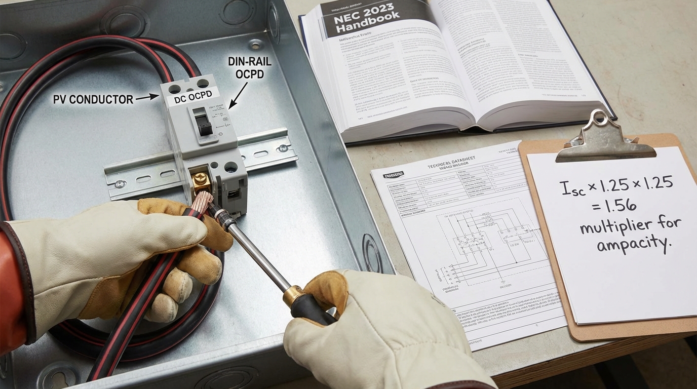
- Determine Maximum Current from Isc: Per NEC 690.8(A), the maximum current of a PV source circuit is the sum of the parallel module Isc ratings multiplied by 125% (1.25). This first 125% factor accounts for solar irradiance levels that can exceed standard test conditions, causing the modules to produce more current than their Isc rating.
- Calculate Required Conductor Ampacity: Per NEC 690.8(B), conductors are sized to carry at least 125% (1.25) of the maximum current calculated in Step 1. This second 125% factor is because PV systems are considered a continuous load. The combined effect is a total multiplier of 1.56 (1.25 x 1.25).
- Apply Correction and Adjustment Factors: The conductor’s ampacity must be adjusted for conditions of use. This is where you apply temperature correction factors for conductors based on the highest expected ambient temperature (NEC Table 310.16) and adjustment factors if more than three current-carrying conductors are bundled in a raceway. For conductors on a rooftop, additional temperature adders may be required per NEC 310.15(B)(3)(c). For a full guide, see our article on how to calculate wire ampacity derating.
- Select Conductor from Ampacity Tables: Using the final required ampacity after all corrections, select the appropriate conductor size from a wire ampacity chart, such as NEC Table 310.16. For detailed guidance, review our tutorial on how to use NEC Table 310.16. The chosen conductor must have an ampacity equal to or greater than your calculated requirement.
Sizing the Overcurrent Protective Device (OCPD)
Sizing the OCPD for PV systems, such as fuses or circuit breakers, follows a similar logic. According to NEC 690.9(B), the OCPD rating must not be less than the maximum current calculated in Step 1 (Isc x 1.25). For example, if three parallel strings have a combined Isc of 30A, the maximum current is 37.5A (30A x 1.25). The OCPD must be at least 37.5A. In this case, you would select the next standard size up, such as a 40A breaker. If you needed to protect a larger system, you might use a 50 amp breaker or higher, provided the calculation supports it. The OCPD rating must not exceed the final, derated ampacity of the conductor it protects. For more on this, see our guide on how to size a circuit breaker.
Other Critical Considerations for Code-Compliant Solar Installations
Beyond the core calculations, a professional installation requires attention to several other factors that impact safety and performance. These elements are frequently scrutinized during inspections.
- Voltage Drop for Solar Circuits: While the NEC does not set a mandatory limit, excessive voltage drop reduces system efficiency. It’s best practice to keep voltage drop for solar circuits under 2-3%. This may require using a larger conductor than the minimum required for ampacity, especially on long wire runs. A voltage drop calculator is a useful tool for this analysis.
- Inverter Output Circuit Requirements: The AC conductors from the inverter to the point of connection are sized differently. According to NEC 705.12, these conductors are typically sized based on 125% of the inverter’s continuous output current rating.
- Rapid Shutdown System Compliance: NEC 690.12 mandates rapid shutdown to protect first responders. Conductor routing and component selection are integral to achieving rapid shutdown system compliance, as specific conductors within a defined boundary must be de-energized to safe voltage levels within seconds.
- Equipment Grounding for Solar: Proper equipment grounding for solar installations is a critical safety measure detailed in NEC 690, Part V, and Article 250. This protects against shock hazards and is essential for the proper operation of ground-fault protection devices.
These calculations are foundational for any licensed electrician in the solar field. To truly master them and stay current with the ever-evolving NEC 2023 solar code, consider advancing your knowledge with dedicated training. Master critical solar calculations. Enroll in our NEC for Solar course to explore these topics and more through our expert-led online electrical courses.
Frequently Asked Questions (FAQ)
What are the main factors for sizing PV conductors according to the solar panel wiring code?
The primary factors for sizing PV conductors are the module’s short-circuit current (Isc), applying two 125% multipliers (for a total of 1.56x) per NEC 690.8 calculations, and then applying correction factors for ambient temperature and the number of conductors in a raceway (conduit fill).
How do you calculate the required ampacity for PV output circuit conductor sizing?
For a DC PV output circuit conductor sizing (the circuit that combines multiple source circuits), you first sum the maximum currents (Isc x 1.25) of all parallel source circuits. Then, you multiply that total by another 125% to determine the minimum conductor ampacity before applying any correction factors for conditions of use.
Why are there two 125% factors in NEC 690.8 calculations?
The first 125% factor (applied to the module Isc) accounts for increased irradiance, where sunlight intensity can cause modules to temporarily produce more current than their rating. The second 125% factor treats the PV system as a continuous load (producing for 3 hours or more), which is a standard safety requirement in the NEC for sizing conductors and OCPDs. The informational note in NEC 690.8 acknowledges this results in a 1.56 multiplier.
Does the NEC have different rules for inverter output circuit requirements?
Yes. The inverter output circuit requirements are covered under NEC Article 705. The AC conductors on the output side of the inverter are sized based on the inverter’s maximum continuous output current rating, typically multiplied by 125%. This is different from the DC side, which is based on the PV modules’ short-circuit current rating (Isc).
Continuing Education by State
Select your state to view board-approved continuing education courses and requirements:
Disclaimer: The information provided in this educational content has been prepared with care to reflect current regulatory requirements for continuing education. However, licensing rules and regulations can vary by state and are subject to change. While we strive for accuracy, ExpertCE cannot guarantee that all details are complete or up to date at the time of reading. For the most current and authoritative information, always refer directly to your state’s official licensing board or regulatory agency.
NEC®, NFPA 70E®, NFPA 70®, and National Electrical Code® are registered trademarks of the National Fire Protection Association® (NFPA®)
You may also like

Colorado Electrical Licensing Requirements and Reciprocity Guide

Standby Generators in DE: Navigating Coastal Storm Regulations
