A Guide to Installing and Supporting Electrical Cable Trays

Understanding the Fundamentals of Cable Tray Systems
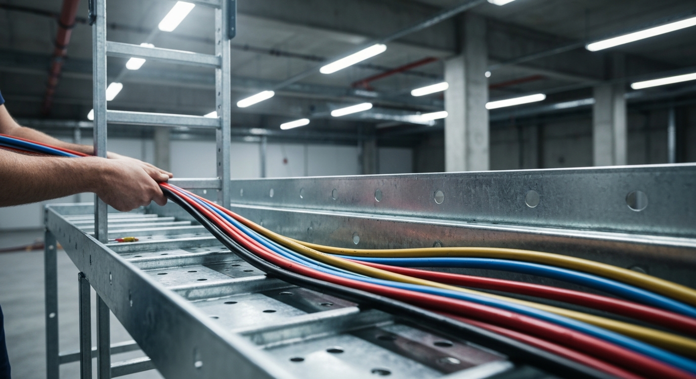
As a professional electrician, you know that managing large volumes of conductors efficiently and safely is a primary challenge in commercial and industrial projects. An electrical cable tray system serves as a rigid structural raceway designed to support and route electrical cables and wires. Unlike a simple wire trough, which is typically a covered channel for shorter runs, cable trays provide a comprehensive support system for complex wiring paths over long distances. A well-planned cable tray installation not only organizes conductors but also provides protection and makes future maintenance and upgrades significantly easier.
Types of Cable Trays: Ladder Tray Versus Ventilated Trough and More
Selecting the appropriate type of tray is the first step in any project. The choice depends on the application, cable types, and environmental conditions.
Ladder Tray
Ladder trays, with their two side rails connected by rungs, are the most common type. They offer excellent ventilation, which is crucial for heat dissipation, and the rungs provide convenient anchor points for tying cables. This design is ideal for power cables and other large-diameter conductors.
Ventilated Trough
A ventilated trough tray provides more continuous support for cables than a ladder tray, thanks to a solid bottom with ventilation holes. The debate of ladder tray versus ventilated trough often comes down to the balance between support and heat dissipation. Ventilated troughs are excellent for smaller control and instrumentation cables that may sag between the rungs of a ladder tray.
Composite Cable Trays
For environments with corrosive chemicals or high moisture, composite cable trays made from fiberglass-reinforced plastic (FRP) are a superior choice. They offer excellent resistance to corrosion and are non-conductive, providing an extra layer of safety in specific applications.
The Blueprint for a Compliant Cable Tray Installation: NEC Article 392
The National Electrical Code (NEC) is the ultimate authority for any cable tray installation. Specifically, NEC Article 392 governs the use, installation, and construction specifications for these systems. This article details everything from permitted uses and cable types to fill capacities and grounding. A deep understanding of this article is non-negotiable for compliance. It provides the framework for ensuring conductors are adequately protected, similar to how NEC rules dictate how open conductor installations are protected from physical damage.
Planning and Support Structures
The mechanical integrity of a tray system is just as important as the electrical components within it. Proper planning begins with understanding the load requirements and selecting the right support method.
- NEMA VE 1 Standards: Always specify trays that conform to NEMA VE 1 standards. This ensures the product meets rigorous manufacturing and performance criteria for load-bearing capacity and materials.
- Cable Tray Support Span: The distance between supports is a critical calculation. The cable tray support span must be determined based on the manufacturer’s load capacity chart and the total anticipated weight of the cables.
- Support Methods: Common support methods include trapeze hangers, which are used for ceiling suspensions, and cantilever wall brackets, which are mounted directly to walls for runs along vertical surfaces. The choice depends on the building structure and the planned tray route.
Step-by-Step Guide to Cable Fill Calculations
Overfilling a cable tray is a serious code violation that can lead to conductor overheating and damage. Proper cable fill calculations are mandated by NEC 392.22. Here is a simplified process:
- Identify Cable Types and Areas: Determine the types of cables to be installed (e.g., multiconductor, single conductor) and find their approximate cross-sectional area (in square inches) from manufacturer spec sheets or NEC Chapter 9, Table 5.
- Determine Maximum Fill Area: Consult NEC Table 392.22(A) to find the maximum permissible fill area for the specific width and type of your cable tray.
- Sum the Cable Areas: Add up the cross-sectional areas of all cables planned for the tray section.
- Verify Compliance: The total area from Step 3 must not exceed the maximum fill area from Step 2.
- Consider Ampacity: Be aware that high-density fills can necessitate conductor ampacity derating as outlined in NEC 310.15. Proper spacing and fill are key to maintaining full current-carrying capacity.
Mastering these calculations is a core skill for any professional. Learn the essentials of commercial and industrial wiring methods to ensure every installation is safe and compliant.
Conductor Installation and Management
Once the tray is installed, the focus shifts to routing the conductors safely and effectively.
Best Practices for Cable Pull Through
A smooth cable pull through is essential to prevent jacket abrasion and conductor damage. Use appropriately placed rollers, sheaves, and pulling lubricants. Plan your pull to have the fewest bends possible and always monitor tension. Well-executed cable pull-throughs protect the integrity of the entire electrical system.
Tying Cables and Cable Segregation
Properly tying cables helps maintain organization and spacing but must be done correctly. Ties should not be over-tightened, as this can deform cable jackets. The material of the tie is also important; for instance, NEC rules for plenum spaces have specific requirements, impacting how 2023 NEC rules affect plenum cable tie selection. Furthermore, cable segregation is often required. Use solid metal dividers to separate power cables from control or data cables to prevent electromagnetic interference (EMI). This is especially critical when dealing with different voltage classes, as the rules for medium voltage cable installations are distinct and demand strict separation.
Essential System Components and Transitions
A complete system relies on a variety of fittings and components to navigate a building’s architecture.
- Conduit to Tray Transitions: All connections must be made with listed fittings. When handling conduit to tray transitions, ensure proper bushings and grounding connections are used, and focus on securing and supporting conduits correctly as they approach the tray.
- Expansion Joints: For long, straight runs, expansion joints are necessary to accommodate the thermal expansion and contraction of the metal tray, preventing buckling and stress. The specific need for expansion joints is determined by the length of the run and the expected temperature variation, as outlined in NEMA VE 2 and manufacturer guidelines, not a fixed distance.
- Firestopping Systems: When a cable tray system penetrates a fire-rated wall or floor, it is absolutely critical to restore the fire rating. This requires installing approved firestopping systems specifically designed for cable trays, such as pillows, blocks, or sealant compounds.
Critical Safety: Bonding and Grounding Requirements
Safety and code compliance hinge on proper electrical continuity. The bonding and grounding requirements for cable trays are detailed in NEC 392.60. Steel or aluminum cable tray systems can be used as equipment grounding conductors (EGCs) provided they are marked as such by the manufacturer and all sections and fittings are bonded together with listed connectors or bonding jumpers. This creates a continuous, low-impedance path for fault current.
Primary Sources for Cable Tray Installation
- National Electrical Code (NEC) Article 392
- NEMA VE 1 / CSA C22.2 No. 126.1 – Metal Cable Tray Systems
- NEMA VE 2 – Cable Tray Installation Guidelines
Frequently Asked Questions
- What is the most important consideration for a successful cable tray installation?
- The most critical aspect of a cable tray installation is comprehensive planning. This includes selecting the correct tray type for the environment and cable load, accurately calculating the cable tray support span, and strictly adhering to the guidelines within NEC Article 392 from start to finish.
- How do you perform cable fill calculations for a mixed-use cable tray?
- For a tray with a mix of multiconductor cables and single conductors, NEC 392.22 provides specific rules. You must calculate the sum of the diameters of all single conductor cables 1/0 AWG and larger and compare it to the maximum fill value for that tray width, as specified in NEC 392.22(B). Then, you calculate the sum of the cross-sectional areas of the multiconductor cables (and any smaller single conductors) and ensure the total does not exceed the remaining allowable fill area. These detailed cable fill calculations prevent overheating.
- What are the main differences in a ladder tray versus ventilated trough installation?
- The main difference in a ladder tray versus ventilated trough installation lies in cable support and ventilation. Ladder trays offer superior ventilation and are easier for securing large cables. Ventilated troughs provide more continuous support, which is better for smaller, more sensitive cables that could sag. The installation mechanics (supports, grounding) are largely the same, but the choice impacts cable layout and heat management.
- Can an electrical cable tray be used as an Equipment Grounding Conductor (EGC)?
- Yes, an electrical cable tray can serve as an EGC if it meets all bonding and grounding requirements outlined in NEC 392.60. The system must be identified for grounding, have securely bonded sections, and be electrically continuous. This eliminates the need to run a separate EGC, saving time and material.
Continuing Education by State
Select your state to view board-approved continuing education courses and requirements:
Disclaimer: The information provided in this educational content has been prepared with care to reflect current regulatory requirements for continuing education. However, licensing rules and regulations can vary by state and are subject to change. While we strive for accuracy, ExpertCE cannot guarantee that all details are complete or up to date at the time of reading. For the most current and authoritative information, always refer directly to your state’s official licensing board or regulatory agency.
NEC®, NFPA 70E®, NFPA 70®, and National Electrical Code® are registered trademarks of the National Fire Protection Association® (NFPA®)
You may also like

Colorado Electrical Licensing Requirements and Reciprocity Guide

Standby Generators in DE: Navigating Coastal Storm Regulations
