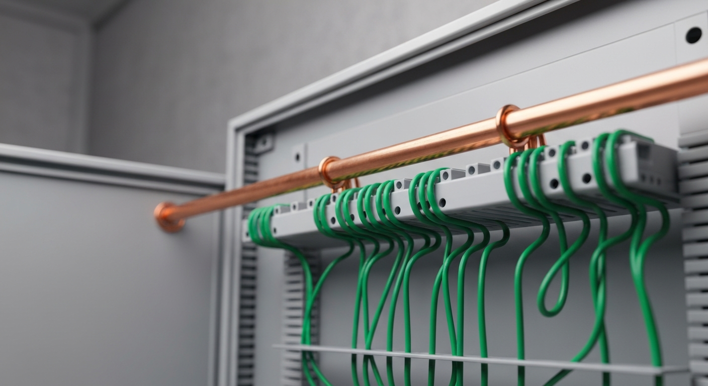
Grounding vs. Bonding: A Deep Dive into NEC Article 250
For licensed electricians, the discussion of grounding vs bonding is fundamental to safe and compliant electrical installations. While often used interchangeably in casual conversation, these two concepts serve distinct, critical purposes defined within NEC Article 250. Understanding this difference is not just a matter of code compliance; it’s the bedrock of protecting equipment and, more importantly, human life. Grounding primarily connects an electrical system to the earth, stabilizing voltage and protecting against external events like lightning. Bonding, conversely, joins all non-current-carrying metallic components to create a low-impedance path known as the effective ground-fault current path. This path is essential for ensuring that an overcurrent protection device can operate swiftly during a fault. This article provides a deep dive into these concepts, the key components like the equipment grounding conductor (EGC), and the specific NEC Article 250 requirements you must know.
Understanding the Core Concepts: What is Grounding?
Grounding is the act of connecting an electrical circuit or equipment to the earth or to a conductive body that serves in place of the earth. The primary purpose of grounding, as detailed throughout NEC 250, is to limit the voltage imposed by lightning, line surges, or unintentional contact with higher-voltage lines. By establishing a reference to earth potential, it stabilizes the voltage to ground during normal operation.
This connection is achieved through the grounding electrode system, which can consist of ground rods, concrete-encased electrodes (Ufer grounds), or qualified metal water pipe grounding. The conductor that makes this connection, running from the service equipment to the electrode, is the grounding electrode conductor (GEC). It is crucial to remember that the earth itself is a poor conductor and is not intended to be the path for clearing a ground fault. Its role is voltage stabilization.
Defining the Other Side of the Coin: What is Bonding?
Bonding is arguably the more critical of the two concepts for personnel safety. Bonding is the permanent joining of metallic parts to form an electrically conductive path. Its purpose is to ensure electrical continuity and the capacity to safely conduct any fault current likely to be imposed. This creates what the code calls the effective ground-fault current path.
This low-impedance path is designed to carry fault current from the point of a fault back to the electrical source. This large current flow causes the circuit breaker or fuse to open quickly, facilitating proper overcurrent protection device operation and de-energizing the circuit. Without effective bonding, a faulted piece of equipment could become energized at a lethal voltage, waiting for a person to complete the circuit to ground. The primary conductor used for this purpose is the equipment grounding conductor (EGC). Proper electrical service bonding is the foundation of a safe installation.
Key Components in the NEC 250 Grounding and Bonding System
Article 250 of the National Electrical Code outlines a family of conductors and jumpers, each with a specific job. Confusing them can lead to dangerous code violations.
The Grounded Conductor (The Neutral)
The grounded conductor, typically the neutral in single-phase systems, is a current-carrying conductor that is intentionally connected to ground at the service. While it is grounded, it is fundamentally different from a grounding conductor. It completes the circuit for normal operation. The rules for grounded conductor sizing are found in NEC Article 220 for load calculations and Article 250 for specific applications. It’s critical to distinguish between all the grounded conductors on a project and the equipment grounding conductors.
The Grounding Electrode Conductor (GEC)
As mentioned, the GEC electrical component connects the grounded conductor at the service disconnect to the grounding electrode system. The required grounding electrode conductor size is determined not by the overcurrent device rating, but by the size of the ungrounded service-entrance conductors, as specified in NEC Table 250.66. You will often see this referenced as 250.66 NEC in code discussions.
The Equipment Grounding Conductor (EGC)
The equipment grounding conductor (EGC) is the “safety wire.” It is not intended to carry current during normal operation. Its sole purpose is to bond non-current-carrying metal parts of equipment, raceways, and enclosures together and back to the system ground. This creates the low-impedance path for fault current. The EGC must be a continuous grounding conductor path. Sizing for the EGC is found in NEC Table 250.122, and is based on the rating of the circuit’s overcurrent protection device. Recent code cycles have introduced important changes to EGC sizing and splicing in the 2023 NEC that all electricians should be aware of, especially when dealing with retrofit work like grounding non-grounding type receptacles.
Critical Jumpers: Main Bonding Jumper, System Bonding Jumper, and Supply-Side Bonding Jumper
Three key jumpers complete the system:
- Main Bonding Jumper: This is the connection at the service between the grounded conductor and the equipment grounding conductor. It establishes the critical link that allows fault current on the EGC to return to the source via the neutral.
- System Bonding Jumper: This performs the same function as a main bonding jumper, but for separately derived systems (e.g., a transformer). It connects the grounded conductor to the equipment ground bus within that system’s enclosure.
- Supply Side Bonding Jumper: This is a conductor installed on the supply side of a service disconnect that ensures the required electrical conductivity between metal parts. Proper sizing and installation of the supply-side bonding jumper are critical for safety.
Practical Application: Sizing Conductors per Article 250 of the National Electrical Code
Proper ground conductor sizing is non-negotiable. Using the correct NEC grounding table is a daily task for electricians. The process for sizing grounding conductors differs based on the conductor’s role.
Step-by-Step: Sizing an Equipment Grounding Conductor (EGC) using NEC Table 250.122
- Identify OCPD Rating: Determine the amp rating of the fuse or circuit breaker protecting the circuit.
- Consult NEC Table 250.122: Find this amp rating in the left-hand column of this essential nec grounding chart.
- Determine Conductor Size: Read across to the corresponding columns to find the minimum required size for your copper or aluminum EGC.
- Check for Adjustments: Review NEC 250.122(B) for situations where the EGC must be increased in size, such as for voltage drop on the ungrounded conductors.
A Note on Sizing the Grounding Electrode Conductor with NEC Table 250.66
Remember that sizing grounded conductor rules differ from EGC sizing. GEC sizing, per NEC Table 250.66, is based on the size of the largest ungrounded service-entrance conductor. This is because the GEC’s job isn’t to clear faults but to handle lightning and surges, which relate to the overall service size.
Common Pitfalls and NEC Article 250 Requirements
Even seasoned professionals can make mistakes with grounding and bonding, often with serious consequences. One of the most critical areas to watch is the creation of parallel paths for neutral current.
Avoiding Objectionable Currents (Neutral OBJ)
The code uses the term objectionable currents to describe neutral current flowing on the grounding and bonding paths. This is a hazardous situation, often caused by improperly connecting the grounded conductor (neutral) to the equipment ground anywhere downstream from the main bonding jumper. This practice, sometimes seen in older installations for ranges and dryers, creates parallel paths for return current, meaning metal enclosures and raceways can become energized during normal operation. The 2023 code has continued to clarify and enforce rules related to this, including providing simplified grounding for ranges and dryers to eliminate this hazard in modern installations. The term neutral obj often comes up in field discussions as shorthand for this critical safety concept.
- Key Takeaway: The neutral and ground should only be connected at one point in a system: at the service disconnect (via the main bonding jumper) or at a separately derived system’s source (via the system bonding jumper).
- Key Takeaway: Always ensure the EGC electrical system provides a continuous grounding conductor path from the equipment back to the panel.
- Key Takeaway: Double-check your electrical service bonding to confirm all required jumpers are installed correctly and are of the proper size.
- Key Takeaway: When in doubt, always refer directly to article 250 of the national electrical code for the most current and specific rules.
The complexities of grounding vs bonding are vast, but mastering them is the mark of a true professional. To elevate your expertise and ensure every installation is safe and compliant, you need to go beyond the basics. Master NEC Article 250 with our specialized grounding and bonding course.
Primary Sources
This article is based on the requirements found in the National Electrical Code® (NEC), which is developed and published by the National Fire Protection Association (NFPA). For official information, please refer to:
Frequently Asked Questions (FAQ)
Q1: What is the main difference in the grounding vs bonding debate according to NEC 250?
The main difference in grounding vs bonding is their purpose. Grounding connects the electrical system to the earth to stabilize voltage and protect from lightning. Bonding connects all metallic, non-current-carrying parts together to create an effective ground-fault current path, which ensures circuit breakers trip quickly during a fault. Both are required by NEC 250, but they solve different problems.
Q2: How do I properly size a grounding electrode conductor using NEC Table 250.66?
To size a grounding electrode conductor, you must first determine the size of the largest ungrounded service-entrance conductor(s). With that information, you refer to NEC Table 250.66. Find your service conductor size in the left columns and read across to find the minimum required size for the copper or aluminum GEC. This differs from EGC sizing, which uses NEC Table 250.122.
Q3: What is an effective ground-fault current path and why is it so critical for safety?
An effective ground-fault current path is an intentionally created, low-impedance conductive path designed to carry current from the point of a ground fault back to the electrical source. It is critical because this path allows a massive amount of fault current to flow, which causes the overcurrent protection device operation (breaker or fuse) to happen almost instantaneously, de-energizing the circuit and preventing electrocution or fire.
Q4: Can the grounded conductor (neutral) be used as an equipment ground?
No, not in modern wiring. Using the grounded conductor (neutral) as an equipment ground downstream of the service disconnect is a major code violation that creates objectionable currents on metal parts. The neutral and ground systems are only permitted to be connected at the service disconnect via the main bonding jumper or at a separately derived system via a system bonding jumper.
Continuing Education by State
Select your state to view board-approved continuing education courses and requirements:
Disclaimer: The information provided in this educational content has been prepared with care to reflect current regulatory requirements for continuing education. However, licensing rules and regulations can vary by state and are subject to change. While we strive for accuracy, ExpertCE cannot guarantee that all details are complete or up to date at the time of reading. For the most current and authoritative information, always refer directly to your state’s official licensing board or regulatory agency.


