Grounding Electrode Connections: Do’s and Don’ts in NEC 2023
DO: Understand the Grounding Electrode System’s Purpose
Before making any connections, it’s crucial to understand the ‘why.’ The Grounding Electrode System (GES), covered in Article 250 Part III, is not primarily for clearing breakers during a ground fault—that’s the job of the Equipment Grounding Conductor (EGC). Instead, the GES connects the entire electrical system to the earth to stabilize voltage during normal operation and provide a path to dissipate energy from lightning or high-voltage line-to-ground faults. The list of allowable grounding electrode system components is detailed in NEC 250.52 grounding electrodes, and includes items like metal underground water pipes, ground rings, and rod and pipe electrodes. If any of these are present at a structure, they must be bonded together to form the system.
DON’T: Rely Solely on a Water Pipe Grounding Electrode
A metal underground water pipe grounding electrode is often the first choice due to its effectiveness. However, a major “don’t” is to use it as the only electrode. NEC 250.53(D)(2) requires you to install one or more supplemental grounding electrodes. The reason is practical: what if the metal water main is later replaced with plastic piping? Without a supplemental electrode, the entire grounding system would be compromised. This is why you must always add a supplemental electrode, such as a ground rod or a concrete-encased electrode (Ufer ground), to ensure long-term system integrity.
DO: Master Your Jumper Requirements
The jumpers at the service are the heart of the fault-clearing system. The main bonding jumper requirements are critical; this jumper connects the grounded conductor (neutral) to the equipment grounding conductor bus at the service disconnect, ensuring a low-impedance path for fault current to return to the source. Similarly, the supply-side bonding jumper serves the same purpose for connections made on the line side of the service disconnect. Sizing these jumpers correctly, typically using Table 250.102(C)(1), is a fundamental “do” for ensuring that overcurrent devices operate swiftly during a fault.
DON’T: Guess on Grounding Electrode Conductor Sizing
One of the most common areas of confusion is Grounding Electrode Conductor (GEC) sizing. The primary rule, found in NEC 250.66, is to size the GEC based on the size of the service-entrance conductors, using Table 250.66. However, there are powerful exceptions you must know. For example, the GEC to a rod, pipe, or plate electrode isn’t required to be larger than 6 AWG copper. For a GEC connected solely to a concrete-encased electrode (Ufer ground), the conductor need not be larger than 4 AWG copper. Misinterpreting these rules can lead to oversized, expensive installations or, worse, undersized and unsafe ones. For a detailed breakdown of these critical rules, it’s beneficial to review guidance on how GEC sizing rules changed in the 2023 NEC.
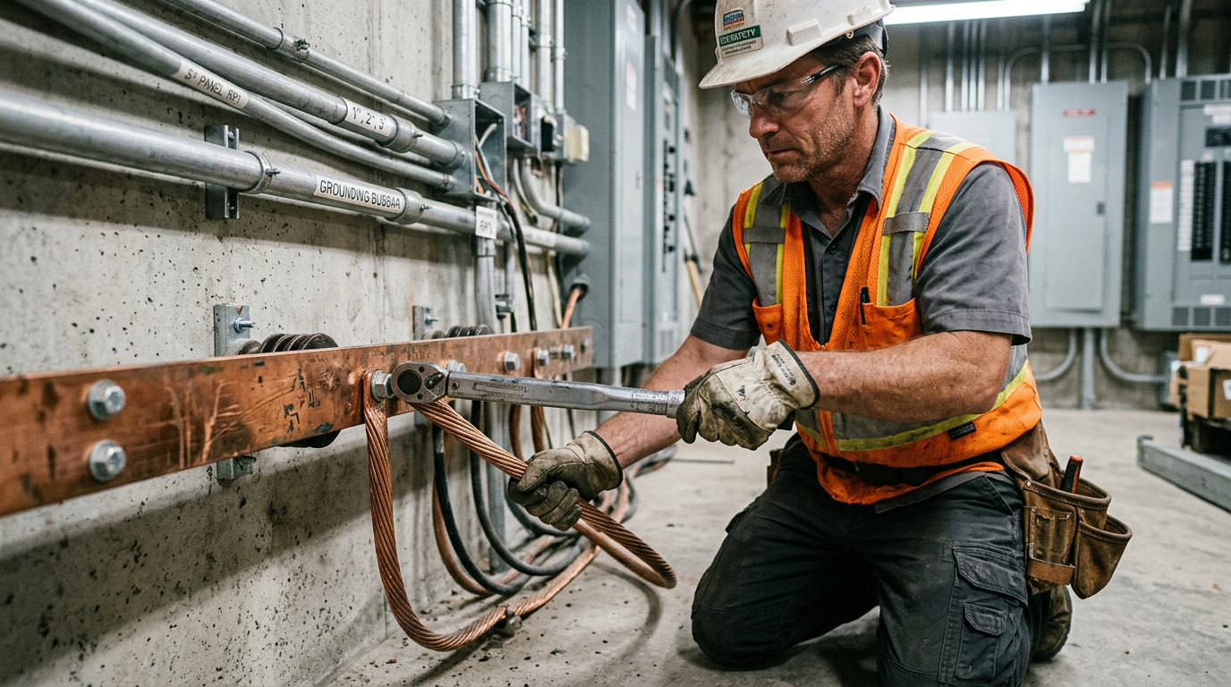
DO: Use Proper Grounding Clips and Fittings
The integrity of your grounding system is only as strong as its weakest link. This makes the choice and installation of grounding clips and fittings a critical step. According to NEC 250.70, all connections to grounding electrodes must be made using listed pressure connectors, exothermic welding, or other listed means. These connections must be suitable for the material of the conductor and electrode and, if buried, listed for direct burial. A growing industry trend is the use of corrosion-resistant materials like stainless steel for grounding components to ensure longevity. Using a modern, listed grounding busbar can also provide a reliable, central point for multiple connections.
DON’T: Ignore Intersystem Bonding and Separately Derived Systems
A safe installation requires that all electrical systems share the same ground reference. This is the purpose of the Intersystem Bonding Termination (IBT), required by NEC 250.94. This device provides a dedicated and accessible point for other trades—like telephone, CATV, or satellite dish installers—to connect their systems to your GES. A major “don’t” is allowing these other systems to be connected haphazardly to piping or other unverified points. Also, be mindful of separately derived systems, such as transformers or generators. These create a new source and have their own specific grounding and bonding requirements under NEC 250.30, including their own system bonding jumper. Complex installations like these have unique requirements, and understanding topics like how the 2023 NEC updates impedance grounding systems is vital for ensuring safety and reliability in commercial and industrial settings.
DO: Connect the Dots to EGCs and GFCI Protection
Finally, remember how the GES connects to the rest of the safety system. While the GES stabilizes voltage relative to the earth, the equipment grounding conductor (EGC) is the path that carries fault current back to the source to trip the breaker. These two systems are connected at the main bonding jumper. Additionally, remember that personal safety is enhanced by Ground Fault Circuit Interrupter (GFCI) protection. GFCI devices don’t rely on the EGC to function; they monitor for imbalances in current between the hot and neutral conductors, providing rapid protection against shock even if the grounding path is compromised.
Staying Ahead of the Code
Mastering the do’s and don’ts of nec 2023 grounding and bonding is not just about code compliance—it’s about demonstrating professionalism and a commitment to safety. From correctly sizing jumpers and conductors to ensuring every connection is robust and reliable, the details in Article 250 are what separate a good installation from a great one. The electrical code is constantly evolving. Keep your skills sharp and your knowledge current. Browse our courses at ExpertCE to stay ahead of the curve and lead the industry in safety and expertise.
Related Resources
Continuing Education by State
Select your state to view board-approved continuing education courses and requirements:
Disclaimer: The information provided in this educational content has been prepared with care to reflect current regulatory requirements for continuing education. However, licensing rules and regulations can vary by state and are subject to change. While we strive for accuracy, ExpertCE cannot guarantee that all details are complete or up to date at the time of reading. For the most current and authoritative information, always refer directly to your state’s official licensing board or regulatory agency.
NEC®, NFPA 70E®, NFPA 70®, and National Electrical Code® are registered trademarks of the National Fire Protection Association® (NFPA®)
You may also like

Alabama Electrician License Renewal
AFCI & GFCI Rules in Arkansas: Navigating the Adopted 2020 NEC