System Bonding Jumpers vs. Supply-Side Bonding Jumpers
Answering the Core Question: Key Differences at a Glance
For licensed electricians navigating NEC Article 250, understanding the distinction between a system bonding jumper and a supply side bonding jumper is critical for safety and compliance. The primary difference lies in their location and specific function. A system bonding jumper creates the essential connection between the grounded conductor (neutral) and the equipment grounding conductor (EGC) system at one specific point—either at the service disconnect or the source of a separately derived system. This establishes the effective ground-fault current path for the entire system. Conversely, a supply side bonding jumper is installed on the line side of the service disconnect to bond conductive materials, such as metal raceways or meter enclosures, back to the grounded service conductor. While both are sized according to NEC 250.102(C), their roles in achieving proper service equipment grounding are distinct and not interchangeable.
Foundations First: Grounding vs. Bonding in NEC Article 250
Before dissecting the jumpers, we must solidify the concept of grounding vs. bonding. While often used interchangeably in casual conversation, article 250 of the National Electrical Code treats them as two distinct but related concepts. Grounding is the act of connecting an electrical system or equipment to the earth (ground) itself, primarily for lightning and high-voltage surge protection. The grounding electrode conductor is the key component here. Bonding, on the other hand, is the permanent joining of metallic parts to form an electrically conductive path. Its purpose is to ensure electrical continuity and create a safe, low impedance path for fault current to travel on, allowing overcurrent protection devices to operate. Both the system bonding jumper and the supply side bonding jumper are critical bonding components.
The System Bonding Jumper: Establishing the Fault Clearing Path
The system bonding jumper is arguably one of the most important components in an electrical system’s safety design. Its requirements are detailed in NEC 250.28. Its sole purpose is to connect the equipment grounding conductors of a system to the system’s grounded conductor. This single connection creates the return path necessary for a ground fault to become a short circuit, tripping a breaker or blowing a fuse.
The Main Bonding Jumper at the Service
In most standard services, the system bonding jumper is referred to as the main bonding jumper. It is located within the service disconnect enclosure. It physically connects the neutral bus (where the grounded service conductor terminates) to the equipment grounding bus. Without this jumper, there is no designed path for fault current to return to the source, rendering the overcurrent devices ineffective for ground faults and leaving metal enclosures energized—a severe shock hazard. This connection is fundamental to preventing objectionable current on the grounding system during normal operation by ensuring the connection only happens at one point.
Separately Derived System Bonding
A system bonding jumper is also required for a separately derived system (SDS), such as a transformer or generator. In a separately derived system bonding scenario, the jumper connects the grounded conductor (neutral) created by the SDS to the metal frame of the source and to the equipment grounding conductors of the circuits it supplies. This ensures a local effective ground-fault current path is established for the system derived from that source.
The Supply-Side Bonding Jumper: Bonding on the Line Side
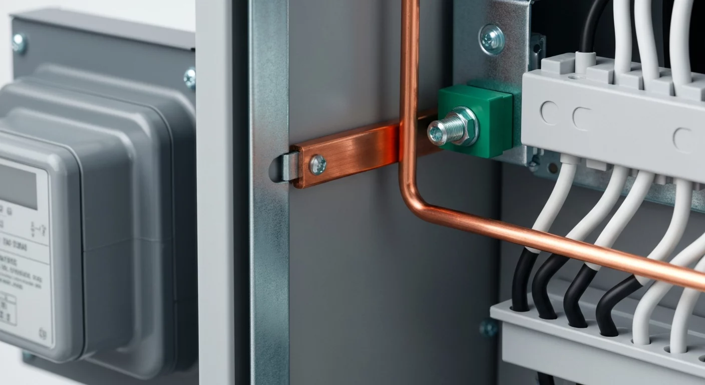
The supply side bonding jumper is a conductor installed on the supply side of any service disconnect. Its job, as outlined in Part III of NEC 250, is to ensure the bonding of conductive raceways, enclosures, and equipment located on the line side of service disconnect. For instance, if you have a metal conduit containing service-entrance conductors between a utility meter enclosure and the service panel, a supply side bonding jumper is required to bond that conduit. It ensures that if a fault occurs on these supply-side components, a low impedance path exists back to the source (the utility transformer), facilitating the operation of the utility’s fuse or overcurrent device. It’s a key part of complete electrical service bonding.
Sizing Jumpers: NEC 250.102(C), NEC Table 250.66, and NEC Table 250.122
A frequent point of confusion is bonding jumper sizing. Both the system bonding jumper and the supply side bonding jumper are sized differently than a standard equipment grounding conductor (EGC). Their size is not determined by the rating of the branch-circuit overcurrent device.
Bonding Jumper Sizing per NEC 250.102(C)
The rules for sizing both jumpers are found in NEC 250.102(C). This section directs you to NEC Table 250.102(C)(1), which is based on the size of the ungrounded service-entrance conductors. For professional electricians, it’s important not to confuse this table with NEC Table 250.66. While the tables are very similar, Table 250.66 is used for sizing the grounding electrode conductor size, and electricians must use Table 250.102(C)(1) as specified for bonding jumpers. This is a critical distinction from sizing an EGC for a branch circuit, which uses NEC Table 250.122 based on the breaker size.
Step-by-Step Sizing Calculation
Here is a simplified process for proper ground conductor sizing for these jumpers, using NEC Table 250.102(C)(1):
- Determine the Conductor Size: Identify the size (in kcmil or AWG) of the largest ungrounded service-entrance conductor or equivalent derived phase conductor for a separately derived system.
- Consult NEC Table 250.102(C)(1): Go to NEC Table 250.102(C)(1). This is the specific table required for sizing these jumpers. Be careful not to confuse it with NEC Table 250.66, which is used for sizing the Grounding Electrode Conductor.
- Find the Minimum Jumper Size: Find your ungrounded conductor size in the left column of the table. The right column will specify the minimum required size for your copper or aluminum bonding jumper. Correctly sizing the bonding jumper is essential for a safe installation.
- Verify and Install: Ensure the jumper is installed to be a continuous grounding conductor path without splices, unless permitted by specific exceptions. The methods for making these connections are just as critical as the sizing, which you can learn more about in our guide on how grounding electrode conductor connections are handled in the 2023 NEC.
Key Differences and Takeaways
Properly applying the rules for these jumpers is a hallmark of a professional installation. While some specialized applications, like those in our lesson on how the 2023 NEC simplifies healthcare facility panelboard bonding, have unique rules, the fundamentals remain.
- Location: The system bonding jumper (or main bonding jumper) is installed at one point: the service disconnect or the source of an SDS. The supply side bonding jumper is installed on the supply (line) side of the service disconnect.
- Purpose: The system bonding jumper establishes the system’s ground-fault return path by connecting the grounded conductors to the EGC system. The supply-side jumper bonds equipment on the line side of the main disconnect.
- Sizing: Both jumpers are sized based on the ungrounded conductor size per NEC 250.102(C), not the overcurrent device rating used for EGCs in NEC Table 250.122.
- Application Scope: The principles of bonding extend to many specific areas, and it’s important not to confuse system bonding with other types, such as the unique rules outlined in our course covering swimming pool equipotential bonding requirements.
Mastering the nuances of NEC 250 is a continuous journey. These bonding jumpers are not just wires; they are life-saving components that form the backbone of a safe electrical installation. Deepen your expertise in grounding and bonding with ExpertCE.
Primary Sources & Official Documentation
For the complete, official text and tables referenced in this article, always consult the source. The rules for grounding and bonding are defined by the National Fire Protection Association (NFPA).
Frequently Asked Questions (FAQ)
What is the main purpose of a supply side bonding jumper according to NEC Article 250?
The main purpose of a supply side bonding jumper is to provide a reliable, low-impedance fault current path for any conductive materials on the line side of the service disconnect. This ensures that if an energized conductor faults to a metal raceway or meter enclosure before the main breaker, the fault current has a path back to the utility source, allowing the utility’s overcurrent protection to operate and clear the fault, preventing shock hazards.
How is bonding jumper sizing for a system bonding jumper different from an equipment grounding conductor (EGC)?
Bonding jumper sizing for a system bonding jumper is based on the size of the ungrounded service or source conductors, as specified in NEC 250.102(C) and its corresponding table (which mirrors NEC Table 250.66). In contrast, the size of an equipment grounding conductor (EGC) for a branch circuit or feeder is determined by the rating of the overcurrent protective device (e.g., the circuit breaker), as specified in NEC Table 250.122.
Can a main bonding jumper and a supply side bonding jumper be the same thing?
No, they are two distinct components with different locations and functions. The main bonding jumper (a type of system bonding jumper) is installed inside the service equipment to create the primary connection between the grounded conductor (neutral) and the equipment grounding system. A supply side bonding jumper is installed before the service equipment, on the line side, to bond metallic parts like conduits that are part of the service entrance.
Where does the NEC discuss the requirements for a separately derived system?
The primary requirements for a separately derived system, including the rules for grounding, bonding, and the installation of the system bonding jumper for that system, are located in NEC Article 250.30. This section details how to establish a new grounding reference for sources like transformers and generators to ensure a proper effective ground-fault current path.
Why is establishing a continuous grounding conductor path so important in electrical service bonding?
Establishing a continuous grounding conductor path is the foundation of electrical service bonding and overall system safety. This unbroken, low impedance path is the designated roadway for dangerous fault current to travel back to its source. Without this continuous path, fault current can energize metal parts of the electrical system that people might touch. A complete path ensures the fault current is high enough to trip a breaker or blow a fuse almost instantly, de-energizing the circuit and preventing fire or electrocution.
Continuing Education by State
Select your state to view board-approved continuing education courses and requirements:
Disclaimer: The information provided in this educational content has been prepared with care to reflect current regulatory requirements for continuing education. However, licensing rules and regulations can vary by state and are subject to change. While we strive for accuracy, ExpertCE cannot guarantee that all details are complete or up to date at the time of reading. For the most current and authoritative information, always refer directly to your state’s official licensing board or regulatory agency.
NEC®, NFPA 70E®, NFPA 70®, and National Electrical Code® are registered trademarks of the National Fire Protection Association® (NFPA®)
You may also like

Colorado Electrical Licensing Requirements and Reciprocity Guide

Standby Generators in DE: Navigating Coastal Storm Regulations
