NEC Derating Explained: A Guide to Conduit Fill Adjustments
NEC Derating Explained: A Guide to Conduit Fill Adjustments
Understanding the nec derating table is fundamental for ensuring safe and compliant electrical installations. Derating is the intentional reduction of a conductor’s allowable ampacity of conductors due to conditions that prevent adequate heat dissipation. The two primary reasons for derating are bundling multiple current-carrying conductors in a raceway and high ambient temperatures. When derating wire in conduit, electricians must use the ampacity adjustment factors found in NEC Table 310.15(C)(1). This process involves starting with the conductor’s ampacity from NEC Table 310.16, counting the number of current-carrying conductors, and applying the corresponding percentage adjustment. Failing to perform these derating calculations correctly can lead to overheating, insulation failure, and significant fire hazards, making this a critical skill for every licensed electrician focused on electrical code compliance.
The Fundamentals of Conductor Ampacity and Derating
Before diving into derating, it’s essential to have a firm grasp of ampacity. As defined by NEC Article 310, ampacity is the maximum current, in amperes, that a conductor can carry continuously under the conditions of use without exceeding its temperature rating. The starting point for determining any conductor’s capacity is NEC Table 310.16. This table provides the baseline allowable ampacities for insulated conductors based on their size (AWG or kcmil), insulation type, and a standard ambient temperature of 86°F (30°C).
For example, when you look up the 12 awg ampacity or ampacity 10 awg, this table is your first stop. The specific awg ampacity is not a single number; it varies based on the conductor’s insulation temperature rating (e.g., 60°C, 75°C, 90°C) and whether it’s copper or aluminum. The concept of termination temperature rating is also critical; a conductor’s ampacity is limited by the lowest temperature rating of any connected termination, device, or conductor in the circuit.
Why Derating is Non-Negotiable: Heat Dissipation and Safety
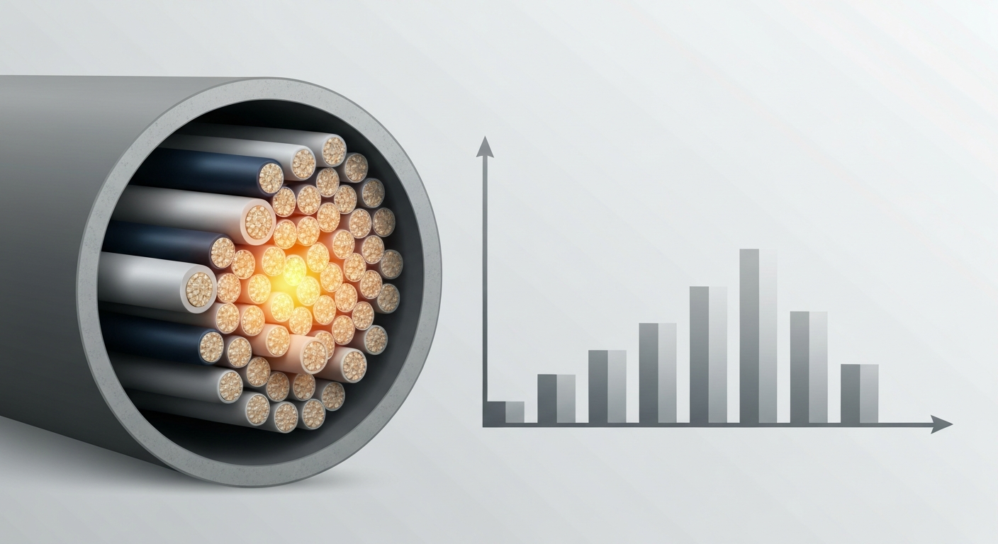
Every current-carrying wire generates heat (I²R losses). In open air, this heat dissipates easily. However, the dynamics change when you bundle conductors together in a conduit. The process of derating wire in conduit is necessary because the conductors in the center of the bundle cannot shed heat as effectively as those on the outside. This leads to a cumulative temperature rise. Proper wire sizing for heat and applying derating factors prevents the conductor’s insulation from reaching a temperature that could cause it to degrade, melt, or ignite—a cornerstone of electrical code compliance. The core issue is managing heat dissipation in conduit to maintain safety.
The Two Primary Derating Scenarios
The National Electrical Code outlines two main conditions that require ampacity adjustments. These factors can apply individually or simultaneously, and a professional electrician must account for both.
Ambient Temperature Correction
When conductors are installed in an environment where the ambient temperature is significantly higher or lower than the 86°F (30°C) baseline used for NEC Table 310.16, an ambient temperature correction is required. For example, conductors run across a hot rooftop or near heat-producing equipment will have their ampacity reduced. The NEC provides specific correction factor tables for these scenarios, which must be applied to the conductor’s baseline ampacity.
Conductor Bundling Derating: Understanding the NEC Derating Table
This is the most common form of derating electricians encounter. When more than three current-carrying conductors are present in a single raceway or cable, you must apply a raceway fill adjustment; the 24-inch length condition applies to single conductors or multiconductor cables not installed in raceways without maintaining spacing for a continuous length (24 in.). This adjustment is mandated by NEC Table 310.15(C)(1), the primary nec derating table. This nec derating chart provides percentage-based ampacity adjustment factors based on the number of conductors. For example, for 4-6 current-carrying conductors, the ampacity must be adjusted to 80% of its original value. This is a critical aspect of conductor bundling derating. While this article focuses on conductor ampacity, it’s important to remember that all parts of an installation must be compliant. For instance, while applying a derate table nec to wires, you must also ensure associated components are correctly sized. You can review how to calculate junction box size with terminal blocks to ensure your entire raceway system is up to code.
Step-by-Step Guide to Performing Derating Calculations
Performing derating calculations accurately is a systematic process. Let’s walk through an example for a conduit containing multiple conductors.
- Determine Starting Ampacity: Begin with NEC Table 310.16. Identify the conductor size, material, and insulation rating. For this example, let’s use 500 kcmil THHN copper, which has a 90°C rating and a baseline ampacity of 430A. We use the 90°C column for derating calculations, even if terminations are rated lower, but the final ampacity cannot exceed the value in the lower-rated column (e.g., 75°C). The initial 500 mcm ampacity is our starting point.
- Count Current-Carrying Conductors: Count the number of current-carrying conductors in the raceway. Let’s assume we have 8. Remember that in a 3-phase, 4-wire wye system, the neutral conductor must be counted as a current-carrying conductor if it carries a significant portion of harmonic currents.
- Find the Adjustment Factor: Refer to the nec derating table, NEC Table 310.15(C)(1). For 7-9 conductors, the adjustment factor is 70%. This is the core data from the wire derating chart.
- Apply the Adjustment: Multiply the starting ampacity by the adjustment factor. 430A * 0.70 = 301A.
- Apply Ambient Temperature Correction (if needed): If the conduit is in a location with an ambient temperature of 100°F, you would apply an additional correction factor. Let’s assume a standard environment for this example.
- Verify Final Ampacity: The new allowable ampacity of conductors is 301A. This value must be greater than or equal to the circuit load, factoring in any requirements for continuous load ampacity (which must be calculated at 125% of the continuous load).
Common Questions: MCA, MOP, and Minimum Circuit Ampacity
In the field, you’ll encounter terms on equipment nameplates that relate directly to wire sizing and overcurrent protection, such as MCA and MOP.
What is Minimum Circuit Ampacity (MCA)?
The question of what is minimum circuit ampacity is common, especially with HVAC units. The mca meaning electrical refers to the minimum wire size ampacity required to safely power a piece of equipment. The mca definition electrical is typically calculated as 125% of the motor’s full-load amperes (FLA) plus 100% of all other loads. Your derated conductor ampacity must meet or exceed the MCA listed on the equipment nameplate.
Understanding MOP Electrical Meaning
The mop electrical meaning is “Maximum Overcurrent Protection.” This value specifies the largest fuse or circuit breaker that can be used to protect the equipment. It is calculated to allow the motor to start without nuisance tripping while still protecting the equipment and conductors from short-circuits and ground faults.
Practical Considerations and Key Takeaways
Mastering ampacity adjustments is a hallmark of a professional electrician. Proper application of the wire derate chart and other NEC rules is crucial for safety. Properly executing these derating calculations is essential. Avoid overheating and code violations. Learn derating rules with ExpertCE.
- Termination Temperature Rating is Key: A 90°C conductor is often limited by 75°C terminations. Your final ampacity cannot exceed the value listed in the 75°C column of Table 310.16, even if you used the 90°C value for the initial calculation.
- Count Conductors Carefully: Miscounting the number of current-carrying conductors is a common mistake that leads to incorrect derating.
- Consider All Factors: Always check for both high ambient temperatures and conductor bundling. When both conditions exist, you must apply both adjustment factors.
- Material Matters: Remember that aluminum wire ampacity is lower than that of copper for the same size conductor, requiring a separate column in Table 310.16.
Primary Sources
For the most accurate and up-to-date information, always refer to the official source for electrical code in your jurisdiction. The information discussed here is based on:
- NFPA 70, National Electrical Code (NEC), 2023 Edition
Frequently Asked Questions about the NEC Derating Table
- What is the primary purpose of an nec derating table?
- The primary purpose of an nec derating table, specifically NEC Table 310.15(C)(1), is to provide adjustment factors to reduce a conductor’s ampacity when multiple current-carrying conductors are bundled in a raceway. This adjustment accounts for the reduced heat dissipation in conduit and prevents conductors from overheating.
- How many current-carrying conductors can be in a conduit before conductor bundling derating is required?
- Conductor bundling derating is required when there are more than three current-carrying conductors in a single raceway or cable. Installations with one to three current-carrying conductors do not require this specific adjustment, though ambient temperature correction may still apply.
- Does the nec derating chart apply to both copper and aluminum wire ampacity?
- Yes, the nec derating chart and its adjustment factors apply to all insulated conductors, regardless of material. The process is the same: you start with the baseline ampacity for the specific material (e.g., copper or the lower aluminum wire ampacity) from NEC Table 310.16 and then apply the adjustment factors from the derating table.
- When do you need to consider both ambient temperature correction and adjustments from the derate table nec?
- You must apply both adjustment factors when both conditions exist. For example, if you are running a conduit with seven current-carrying conductors (requiring a 70% adjustment from the derate table nec) across a rooftop where the ambient temperature requires a 0.91 correction factor, you must apply both. The final ampacity would be the starting ampacity x 0.70 x 0.91.
Continuing Education by State
Select your state to view board-approved continuing education courses and requirements:
Disclaimer: The information provided in this educational content has been prepared with care to reflect current regulatory requirements for continuing education. However, licensing rules and regulations can vary by state and are subject to change. While we strive for accuracy, ExpertCE cannot guarantee that all details are complete or up to date at the time of reading. For the most current and authoritative information, always refer directly to your state’s official licensing board or regulatory agency.
NEC®, NFPA 70E®, NFPA 70®, and National Electrical Code® are registered trademarks of the National Fire Protection Association® (NFPA®)
You may also like

Colorado Electrical Licensing Requirements and Reciprocity Guide

Standby Generators in DE: Navigating Coastal Storm Regulations
