Understanding Multi-Wire Branch Circuits (MWBCs): NEC Guide
What is a Multi-Wire Branch Circuit (MWBC)?
At its core, a multiwire branch circuit is an efficient wiring method that uses two ungrounded conductors from opposite phases of a system and a single, common neutral wiring connection. In a typical 120/240V single-phase system, this means you can supply two 120V circuits using a single 3-conductor (plus ground) cable instead of two separate 2-conductor cables. This historical method, sometimes referred to as an Edison circuit, reduces both material costs and conduit fill.
While MWBCs offer advantages, they demand a higher level of care and code knowledge than standard individual branch circuits. Understanding the specific rules for various branch circuits, from the use of 10-amp circuits to the number required in specialized facilities like assisted living facilities, provides a foundation for appreciating the unique requirements of MWBCs.
The Guiding Principles of NEC 210.4
The National Electrical Code (NEC) provides the essential rules for MWBCs in NEC 210.4. Adherence to this section is non-negotiable for a safe and compliant installation. The code clarifies important details, such as conductor voltage limitations which are fundamental to how an MWBC operates.
Disconnecting Means: Simultaneous Disconnection
Per NEC 210.4(B), each multiwire branch circuit must be provided with a means that will simultaneously disconnect all ungrounded conductors at the point where the branch circuit originates. This is a critical safety feature. If a single-pole breaker were used and only one hot leg was disconnected, the shared neutral would still be part of a live circuit, creating a severe shock hazard for an electrician working on what appears to be a de-energized circuit.
This simultaneous disconnection is achieved in one of two ways:
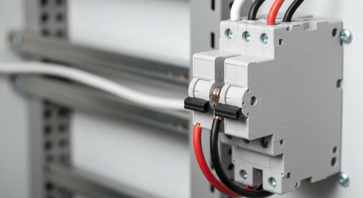
- A two-pole common trip breaker, which is the most robust and recommended method. It ensures that if one circuit overloads, both are disconnected.
- Two single-pole breakers with an approved handle tie. This satisfies the requirement to open both circuits at the same time where the handle tie and breakers are listed/approved for that application, though it does not provide common-trip internal tripping on a single overload event the way a common-trip breaker does.
The Critical Importance of Balancing Loads and Phasing
The magic of an MWBC lies in how the shared neutral handles current. When phasing conductors correctly—that is, connecting the ungrounded conductors to opposite phases (L1 and L2)—the current on the neutral is the difference between the currents on the two hot legs. Proper balancing loads between the two circuits will result in a very low, or even zero, current on the neutral conductor.
However, if the conductors are improperly phased and connected to the same phase, the neutral current becomes the sum of the currents on the hot legs. This creates a dangerous overloaded neutral condition, where the neutral conductor can carry up to twice its ampacity, leading to insulation failure and a significant fire hazard.
Major Hazards: The Open Neutral and Overloaded Neutral
The Dangers of an Open Neutral Hazard
The most infamous risk associated with a multiwire branch circuit is the open neutral hazard. If the shared neutral connection becomes loose or is broken anywhere along the circuit, the two 120V circuits effectively become a 240V series circuit with the connected loads as the series elements. This causes the voltage across the loads to fluctuate based on their resistance. A low-resistance load (like a 1500W hair dryer) could see its voltage drop significantly while a high-resistance load (like a 15W LED light) on the opposite leg could be subjected to a dangerously high voltage, potentially destroying the appliance and creating a fire or shock risk.
Preventing an Overloaded Neutral
The risk of an overloaded neutral is directly addressed by correct installation practices. The key is ensuring the ungrounded conductors terminate on different phases in the panelboard. Modern panelboard arrangements make this intuitive (alternating lugs), but in older panels or during modifications, this must be explicitly verified. Proper common neutral wiring requires pigtailing the neutral conductor where its continuity would be interrupted by the removal of a device so that removing a device does not open the neutral for downstream circuits; this continuity requirement is reflected in the NEC’s rules for multiwire circuits.
Specific Applications and Troubleshooting
The Split-Wire Receptacle
A classic use for an MWBC is the split-wire receptacle, commonly used to provide two separate circuits at a kitchen counter. This involves using a duplex receptacle, breaking the small tab between the two brass-colored hot terminals, and landing each ungrounded conductor on a separate terminal. The shared neutral connects to the silver-colored neutral terminal (whose tab remains intact). For this application, the rule for simultaneous disconnection is absolute; a two-pole common trip breaker is essential for safety.
AFCI Protection for MWBC Installations
Providing AFCI protection for MWBC installations has become more straightforward. Manufacturers produce listed two-pole AFCI and combination AFCI/GFCI breakers designed for shared-neutral circuits. These devices monitor both ungrounded conductors and the shared neutral so the protective function works correctly with the MWBC wiring method.
MWBC Troubleshooting Steps
Effective MWBC troubleshooting requires a systematic approach to identify issues like an open neutral or improper phasing. Here is a basic process:
- Verify Voltages: At the panel, confirm ~240V between the two ungrounded conductors and ~120V from each ungrounded conductor to the neutral bus.
- Check for an Open Neutral: If customers report flickering lights or some devices working while others don’t, suspect an open neutral. At an outlet, carefully measure voltage from hot to neutral under load. Unstable or wildly incorrect voltages are a key symptom of an open neutral hazard.
- Measure Neutral Current: Using a clamp-on ammeter at the panel, measure the current on each ungrounded conductor and the neutral conductor. The neutral current should be the difference between the two hot currents; if it reads approximately the sum, the conductors are improperly phased and require correction immediately to prevent an overloaded neutral.
- Inspect Connections: Check for solid, tight connections at the breaker, neutral bus bar, and all downstream devices and junction boxes. Remember to pigtail neutrals at all device locations where required by the Code so removing a device does not interrupt the neutral for downstream circuits.
Troubleshooting complex branch circuit issues highlights the need for continuous education and a deep understanding of the code. Deepen your understanding of branch circuits with our NEC code courses.
Key Considerations for MWBCs
- Grounded Conductor Sizing: The neutral must be sized to handle the maximum possible unbalanced load. In general the grounded (neutral) conductor is installed with the same ampacity as the ungrounded conductors, but the NEC provides limited exceptions in specific circumstances (for example, certain household range installations). Follow NEC Article 210 conductor-sizing rules and the applicable exceptions when determining neutral size.
- No Single-Pole Switching of Shared-Neutral Loads: Do not use a single-pole GFCI or other device that only protects or controls one ungrounded conductor of an MWBC, because the shared neutral and the way residual-current devices sense current will cause unsafe conditions or nuisance tripping. Use listed 2-pole breakers or devices with common-trip functionality or listed handle ties (where permitted) that provide the required simultaneous disconnection and correct detection for shared-neutral circuits.
- Clear Identification: Identifying conductors as belonging to the same MWBC is important for future service work — label or mark the conductors so that anyone working on the circuit knows they share a neutral and require simultaneous disconnection.
Primary Sources
This article is based on the standards and best practices outlined in the National Electrical Code (NEC). For direct reference, consult the latest edition of NFPA 70.
Frequently Asked Questions (FAQs)
- What is the main danger of a multiwire branch circuit?
- The primary danger is the open neutral hazard. If the shared grounded conductor (neutral) is broken, devices on the circuit are subjected to potentially destructive voltage swings between 0V and 240V, creating a severe shock and fire risk. This is why proper pigtailing of the neutral is mandated and why simultaneous disconnection of the ungrounded conductors at the origin is required by the NEC.
- Does NEC 210.4 require a two-pole common trip breaker for every shared neutral circuit?
- NEC 210.4(B) requires a means for simultaneous disconnection. This can be either a two-pole common trip breaker or two single-pole breakers with an approved handle tie where permitted by the Code and the equipment listing. While both approaches can satisfy the simultaneous-disconnect requirement, a common-trip breaker provides internal combined tripping and is preferred for many applications, especially where a single device is fed by the MWBC, such as a split receptacle.
- How do you prevent an overloaded neutral in a multiwire branch circuit?
- An overloaded neutral is prevented by correct phasing conductors. The two ungrounded (hot) conductors must be connected to opposite phases of the 120/240V service. This ensures that the current on the shared neutral is the difference between the two loads, not the sum. Proper balancing loads across the two circuits also helps minimize neutral current.
Continuing Education by State
Select your state to view board-approved continuing education courses and requirements:
Disclaimer: The information provided in this educational content has been prepared with care to reflect current regulatory requirements for continuing education. However, licensing rules and regulations can vary by state and are subject to change. While we strive for accuracy, ExpertCE cannot guarantee that all details are complete or up to date at the time of reading. For the most current and authoritative information, always refer directly to your state’s official licensing board or regulatory agency.
NEC®, NFPA 70E®, NFPA 70®, and National Electrical Code® are registered trademarks of the National Fire Protection Association® (NFPA®)
You may also like

Colorado Electrical Licensing Requirements and Reciprocity Guide

Standby Generators in DE: Navigating Coastal Storm Regulations
