How to Wire and Troubleshoot MC4 Solar Panel Connectors
Summary: Mastering MC4 Connectors for PV Systems
Properly wiring and troubleshooting mc4 connectors is a critical skill for any electrician working on photovoltaic (PV) systems. Successful installation hinges on precise PV wire termination using a dedicated MC4 crimping tool to create a secure, low-resistance, weather-resistant connection that is intended to provide long-term service when done to manufacturer instructions. The original Stäubli MC4 connectors set the industry benchmark, and it’s important to follow listing and manufacturer guidance about mating parts. When issues arise, effective solar connector troubleshooting involves a systematic approach, including visual inspections, voltage and current checks (solar string testing), and comprehensive PV insulation resistance testing to identify faults. Adhering to manufacturer specifications and the NEC ensures system safety, reliability, and peak performance, preventing common failures and costly downtime. This guide provides the expert-level detail needed to master these essential components of any solar installation.
Understanding MC4 Connectors and Photovoltaic Connector Standards
As a professional electrician, you know that the integrity of any electrical system is only as strong as its weakest link. In solar PV systems, that link is often the connector. The MC4 connector — originally introduced by Multi-Contact (now Stäubli) — is commonly referred to by the shorthand “MC4” and references a nominal 4 mm contact geometry (not a 4 mm² cross-sectional conductor size); it has become the de facto industry connector for many PV module manufacturers. The genuine Stäubli MC4 is renowned for its durability, UV resistance, and low-resistance connection.
It is critical to understand that “MC4” is often used generically, but not all “MC4-style” connectors are identical. Best practice is to use identical, listed mating connectors from the same product family. Mixing brands is not recommended unless the products are specifically listed and documented by the manufacturers as intermateable; otherwise you risk unreliable connections and invalidated listings or warranties. Adherence to photovoltaic connector standards, such as UL 6703 and the connector listing requirements in NFPA 70 (NEC) Article 690, is essential for a safe and code-compliant installation.
The Essential Tools and Materials for Proper PV Wire Termination
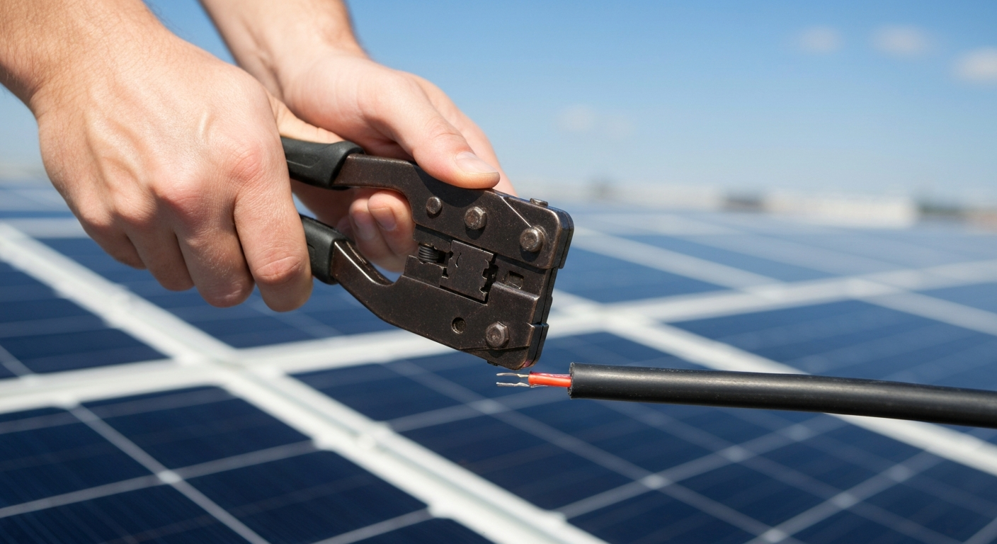
Attempting a PV wire termination without the right equipment is a recipe for disaster. The demands of a high-voltage PV array are vastly different from other low-voltage DC systems. Using pliers or an automotive crimper will create a faulty connection destined to fail. The essential toolkit includes:
- A Professional MC4 Crimping Tool: This is non-negotiable. A dedicated MC4 crimping tool is designed to apply the precise pressure needed to form a gas-tight mechanical crimp between the conductor and the contact pin.
- PV Wire Strippers: These are set to strip the exact length of insulation required without nicking the copper conductors.
- MC4 Assembly/Disassembly Tools: These plastic wrenches are used to properly tighten the gland nut, creating a watertight seal, and to disconnect connectors safely.
- Torque Wrench: While not used for the MC4 gland nut itself in most instructions, a torque wrench is essential for securing connections within combiner boxes, at inverters, and for racking hardware, per manufacturer specifications.
Using improper tools for PV work will guarantee problems down the line.
Step-by-Step Guide to Assembling MC4 Connectors
A flawless connection is achieved through a methodical process. Follow these steps for a reliable, weather-tight termination every time.
- Prepare the PV Wire: Using a PV wire stripper, remove the exact length of insulation specified in the connector’s installation manual. Follow the connector manufacturer’s specified strip length — many MC4 installation guides call for a short stripped length (commonly around 6–8 mm), but always use the dimension in the specific manufacturer’s instructions. Ensure no copper strands are nicked or cut during stripping.
- Slide on the Gland Nut: Before crimping, slide the plastic gland nut over the wire. This is a common mistake that requires you to cut off and waste a newly crimped pin.
- Crimp the Metal Contact Pin: Insert the stripped wire into the barrel of the metal contact pin. Place the pin into the correctly sized die on your MC4 crimping tool and squeeze firmly until the tool’s ratchet mechanism releases. The crimp should be clean, tight, and uniform; a properly made crimp is gas-tight and minimizes resistance and corrosion pathways.
- Insert Pin into Connector Housing: Push the crimped pin into the back of the appropriate male or female connector housing. You should hear and feel a distinct “click” as it locks into place. Give a gentle tug to confirm it is secure.
- Tighten the Gland Nut: Hand-tighten the gland nut onto the connector housing. Use the MC4 assembly tools to finish tightening until the internal gasket is fully compressed and the connection is secure, as specified by the manufacturer. This creates the IP-rated waterproof seal when done per instructions.
- Verify the Connection: Once both male and female connectors are assembled, mate them. They should click together securely. A complete PV system commissioning checklist will include verifying every single one of these connections.
NEC Code for Solar Connectors and Safety Mandates
The National Electrical Code (NEC) Article 690 governs solar installations. The NEC requires connectors and other PV equipment to be listed or field labeled for the application and installed in accordance with manufacturer instructions, which relates directly to the caution about mixing brands. Furthermore, modern code cycles have introduced stringent solar rapid shutdown requirements to enhance firefighter safety (see the rapid shutdown rules in current NEC cycles). These systems often rely on module-level power electronics (MLPEs) that use MC4-style connectors, making their integrity even more critical for the system’s safety functionality. Understanding these rules is just as important as knowing how 2023 NEC rules are changing EV charger installation requirements, as both involve rapidly evolving technologies and safety protocols. The high DC voltages in a PV string present significant shock and arc-flash hazards, demanding a deep understanding of NFPA 70E 2024 battery safety requirements, which share principles with PV DC safety.
Common MC4 Connector Failure Modes and Prevention
Most issues with mc4 connectors are due to installer error. Diagnosing intermittent solar connection problems often leads back to one of these common MC4 connector failure modes:
- Improper Crimping: The #1 cause of failure. A poor crimp creates high resistance, leading to heat, power loss, and eventually, melting or fire.
- Cross-Mating Brands: Incompatible dimensions and materials lead to poor seals and intermittent connections. If connectors are not specifically listed as intermateable, do not mate different brands.
- Under-Tightened Glands: Allows moisture ingress, leading to corrosion and ground faults.
- Damaged O-Rings: The small rubber O-ring on the male connector is crucial for a watertight seal. If it’s missing or damaged, the connection is compromised.
While a loose wire can cause failure in any DC circuit, the consequences in a high-voltage PV array are exponentially more dangerous. Robust, secure connections are paramount to preventing thermal events and ensuring long-term system reliability.
Advanced Solar Connector Troubleshooting Techniques
When a string is underperforming, a methodical approach to solar connector troubleshooting is key. This goes beyond simple visual checks.
First, perform basic solar string testing by checking the open-circuit voltage (Voc) and short-circuit current (Isc) and comparing them to the manufacturer’s data sheet. A significantly low Voc can indicate a failed open connection. For more stubborn issues, PV insulation resistance testing with a megohmmeter (megger) is the definitive way to find faults. This test can identify insulation breakdown that could be caused by a pinched wire or a connector filled with water. A breakdown in PV wire insulation can lead to persistent ground faults and system shutdown. Knowing how the 2023 NEC updates interconnection requirements is also vital, as troubleshooting may involve the point of connection with transfer equipment.
Expanding Your Array: Solar Panel Junction Box Wiring and MC4 Branch Connectors
For larger systems, you will need to wire strings in parallel to increase amperage. This is accomplished using MC4 branch connectors. These components allow you to combine the output of two or more strings into a single homerun to the combiner box or inverter. Proper planning is essential to ensure the combined current does not exceed the wire ampacity or inverter input ratings.
Modern solar panel junction box wiring is greatly simplified because most panels come with pre-attached pigtails and factory-installed mc4 connectors. Your job is to make the connections between modules and to the homerun wiring, reinforcing the need for mastery of the skills discussed here. Mastering these connections is a key part of professional solar work. Get certified for solar panel installation with our comprehensive PV courses.
Primary Sources
- NFPA 70, National Electrical Code (NEC), Article 690
- UL 6703, Standard for Connectors for Use in Photovoltaic Systems
- Stäubli Electrical Connectors – MC4 Installation Manual
Frequently Asked Questions (FAQ)
- What is the most common cause of MC4 connector failure modes?
- By far, the most common cause of MC4 connector failure modes is improper crimping during installation. Using the wrong tool or applying incorrect technique creates a high-resistance point that generates heat, reduces system output, and can become a significant fire hazard over time.
- Are all mc4 connectors compatible with each other?
- No, they are not universally compatible. While many connectors may look like a Stäubli MC4, there are slight dimensional and material differences between manufacturers. Mating connectors from different brands is not recommended unless the connectors are specifically listed and documented as intermateable; doing so otherwise can lead to poor sealing, higher resistance, and may impact product listings and warranties.
- How do you perform solar string testing for a bad MC4 connection?
- Basic solar string testing involves using a CAT-rated multimeter to check the open-circuit voltage (Voc) of the string. If the voltage is significantly lower than the sum of the modules’ Voc ratings, it likely indicates an open or intermittent connection. For more advanced solar connector troubleshooting, I-V curve tracing can pinpoint the exact location and nature of the performance issue, while insulation resistance testing can identify faults caused by moisture ingress in a failed connector.
Continuing Education by State
Select your state to view board-approved continuing education courses and requirements:
Disclaimer: The information provided in this educational content has been prepared with care to reflect current regulatory requirements for continuing education. However, licensing rules and regulations can vary by state and are subject to change. While we strive for accuracy, ExpertCE cannot guarantee that all details are complete or up to date at the time of reading. For the most current and authoritative information, always refer directly to your state’s official licensing board or regulatory agency.
NEC®, NFPA 70E®, NFPA 70®, and National Electrical Code® are registered trademarks of the National Fire Protection Association® (NFPA®)
You may also like

Colorado Electrical Licensing Requirements and Reciprocity Guide

Standby Generators in DE: Navigating Coastal Storm Regulations
