How to Use a Megohmmeter (Megger) to Test Insulation
Why Insulation Resistance Testing is Crucial for Electrical Preventive Maintenance
In the field, a standard multimeter is indispensable. We use it for countless tasks, from getting a simple meter ohm reading to learning how to check a fuse with a multimeter or even how to test a capacitor with a multimeter. However, a multimeter’s low voltage continuity or resistance test cannot adequately stress wire insulation to reveal its true condition. This is where the megohmmeter excels. By applying a much higher DC voltage under controlled procedures, a megohmmeter can reveal leakage and absorption behavior (moisture, contamination, or surface conductive paths) that a multimeter would miss. This proactive testing is a cornerstone of electrical preventive maintenance, allowing technicians to identify and rectify potential faults before they lead to shorts, equipment failure, or dangerous arc-flash events. Regular testing establishes a baseline, and subsequent tests can reveal a downward trend in insulation health, signaling the need for targeted investigation, repair, or replacement.
Essential Tools and Safety Preparations
Before beginning any Megger test procedure, proper preparation is paramount. Your electrician tool bag or electrician tool belt should be equipped for the job, but safety comes first. Always wear the appropriate PPE, including rated electrician gloves, and follow strict lock-out/tag-out (LOTO) procedures to ensure the circuit is fully de-energized. You must then isolate the component under test. This often requires disconnecting conductors, which may mean removing wire nuts, wago wire connectors, or even a large split bolt connector. You’ll need basic hand tools like a flat head screw driver and a reliable wire stripping tool. While some might try a diy wire stripper, a professional automatic wire stripper or a heavy-duty wire stripper machine ensures clean, nick-free conductors for accurate testing.
To isolate components, you may need to work with a vast array of hardware. This can include disconnecting various push in wire connectors, wago wire connectors, or automotive wire connectors. After testing, connections must be cleaned and properly re-secured, and conductors re-insulated with quality electrical tape or liquid electrical tape. It is also important to recognize and bypass certain connection types, like an insulation piercing connector, to get an accurate reading. While specialized tools can speed up preparation, the priority is always precise and safe isolation of the component under test.
The Step-by-Step Megger Test Procedure
Once the circuit is safely prepared, you can begin the test. Following a consistent procedure is key to obtaining reliable and repeatable results.
- Safety, De-energization, and Isolation: Confirm the circuit is de-energized and locked out. Verify with a multimeter. Ensure the equipment or cable to be tested is disconnected from other circuits, loads, and sources. This step is critical for determining normal operating conditions for electrical equipment in NFPA 70e 2024 and establishing an electrically safe work condition.
- Perform DC Test Voltage Selection: Choose the appropriate test voltage based on the equipment’s insulation rating and manufacturer’s guidance. Common field practice is to use 500 V for many low-voltage motors and 1000 V for larger windings, while control wiring is often tested at 250 V or 500 V. Refer to the equipment manufacturer and standards such as IEEE Std 43 for the recommended test voltage for a specific machine.
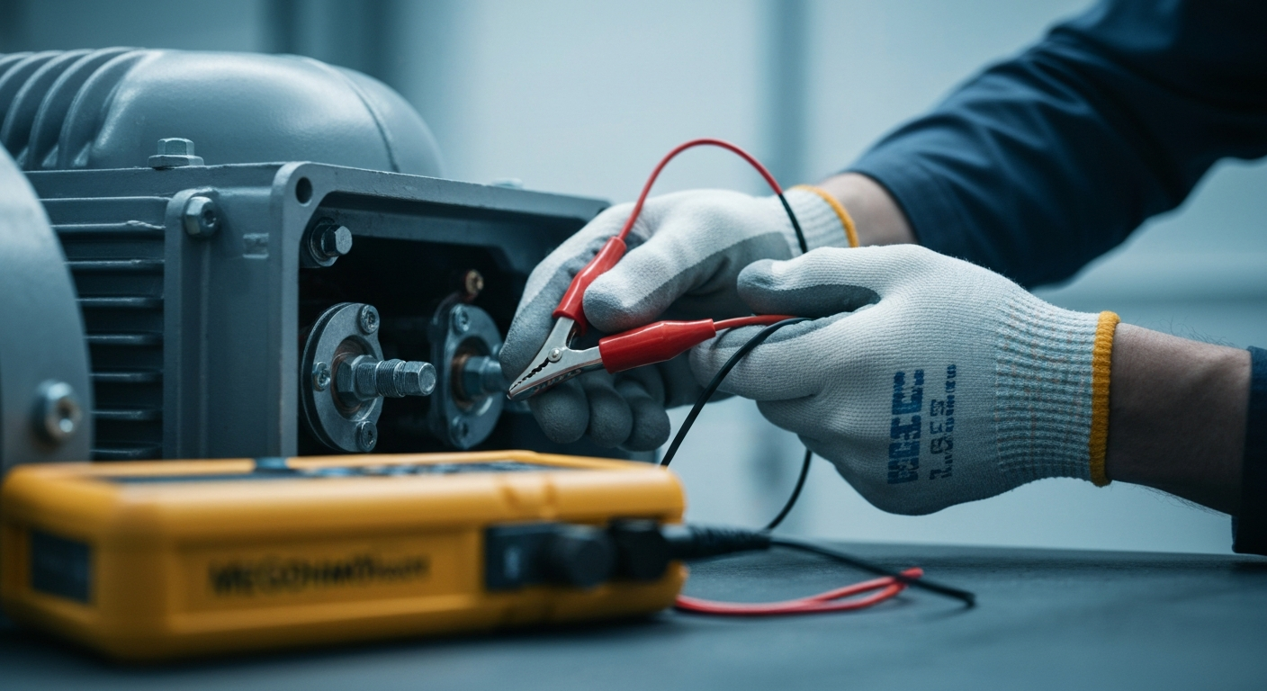
- Connect the Megger Meter: Connect the meter’s ground lead (often black) to a verified system ground (e.g., a grounding bar or motor frame). Connect the test lead (often red) to the conductor you are testing. For phase-to-phase tests connect between the corresponding conductors.
- Apply Voltage and Take a Spot Reading: Apply the test voltage and observe the reading over a consistent time interval. A 60-second reading is a commonly used practical spot reading because leakage currents tend to stabilize during the first minute, but standards also use 30 s, 1 min, and 10 min measurements (for DAR and PI). Be consistent and always record the test duration and environmental conditions.
- Safely Discharge the Circuit: After the test, verify the meter indicates the circuit has been discharged. Many modern megohmmeters automatically provide a discharge path, but you should still confirm zero volts with the meter or use an approved discharge tool before disconnecting test leads or touching conductors.
- Record and Analyze: Record the insulation resistance (in MΩ), the applied test voltage, ambient temperature, and humidity. This data is the foundation for proper megohm reading interpretation and trending for future comparisons.
To go beyond basic readings and truly diagnose the health of motors and cables, you can master advanced diagnostic tools and techniques with our troubleshooting courses.
Understanding Megohm Reading Interpretation and Advanced Tests
A single reading is useful, but its value is limited without context. Effective interpretation requires understanding industry standards and trending data over time. This is especially true when assessing motor conductor sizing and protection, as insulation health is a key factor in a motor’s lifecycle.
Key Considerations for Interpretation:
- Minimum Insulation Resistance Values and Context: There is no single universal MΩ cutoff that fits every motor or cable. The old “one-megohm rule” (1 MΩ per kV + 1 MΩ) is still used as a rule-of-thumb, but IEEE Std 43 provides methods and tables that emphasize temperature correction and time-based ratios (PI and DAR). For many low-voltage motors (for example, 480 V) an insulation resistance of a few megohms after temperature correction may be acceptable, but the best practice is to apply PI/DAR evaluation and trending rather than rely on a single absolute MΩ threshold.
- Temperature Correction Factor: Insulation resistance is highly dependent on temperature. A reading taken at a low ambient temperature will be higher than the same winding tested at elevated temperature. Correct readings to a common baseline (often 40°C) when comparing tests over time, using accepted temperature-correction methods.
- Trending Over Time: The most powerful use of a megohmmeter is for trending. A steady decline in temperature-corrected resistance or degrading PI values over months or years is a clear indicator of insulation deterioration even if absolute MΩ values remain above informal thresholds.
Advanced Insulation Resistance Testing Techniques
For more in-depth diagnostics, particularly on large motors and cables, several advanced tests are used.
Dielectric Absorption Ratio (DAR)
The dielectric absorption ratio (DAR) is commonly the ratio of the 60-second reading to the 30-second reading (60 s / 30 s). Values above about 1.25 indicate normal absorption behavior; lower ratios can indicate moisture or contamination because the resistance does not rise over time as expected.
Polarization Index (PI) Test
The polarization index (PI) is the 10-minute reading divided by the 1-minute reading and is widely used for rotating machinery. General interpretation used in the field is: PI < 1.0 = poor (immediate action required), PI 1.0–2.0 = marginal (investigate), PI ≥ 2.0 = acceptable, and PI ≥ 4.0 often represents excellent insulation. PI is temperature-sensitive and should be corrected and trended for meaningful decisions.
Step Voltage Test and Guard Terminal Use
A step voltage test applies increasing test voltages to detect partial discharges or localized dielectric weakness — a sudden drop in resistance at a higher step can indicate a vulnerability. Using a guard terminal on a megohmmeter (when provided) helps eliminate leakage currents across surfaces so you measure the bulk insulation resistance between the intended conductors rather than surface leakage.
Continuing Education by State
Select your state to view board-approved continuing education courses and requirements:
Disclaimer: The information provided in this educational content has been prepared with care to reflect current regulatory requirements for continuing education. However, licensing rules and regulations can vary by state and are subject to change. While we strive for accuracy, ExpertCE cannot guarantee that all details are complete or up to date at the time of reading. For the most current and authoritative information, always refer directly to your state’s official licensing board or regulatory agency.
NEC®, NFPA 70E®, NFPA 70®, and National Electrical Code® are registered trademarks of the National Fire Protection Association® (NFPA®)
You may also like

Colorado Electrical Licensing Requirements and Reciprocity Guide

Standby Generators in DE: Navigating Coastal Storm Regulations
