How to Install an Electrical Pull Box: NEC Rules & Sizing
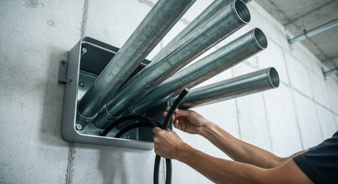
Properly installing electrical pull boxes is a critical skill for any licensed electrician, ensuring that installations are safe, compliant, and maintainable. The primary function of a pull box is to facilitate the installation of conductors within complex raceway systems by providing access points to reduce wire pulling friction over long distances or through multiple bends. Sizing is governed by NEC Article 314, particularly section 314.28 for conductors 4 AWG and larger. Accurate pull box sizing calculations are mandatory to provide adequate space for conductors and prevent damage to their insulation during installation. These calculations differ based on whether the conductors run straight through the box (a straight pull) or change direction (an angle or U-pull), with specific rules for each to ensure code compliance and system integrity.
The Role of Electrical Pull Boxes in Modern Raceway Systems
In the electrical trade, understanding the precise conduit meaning and function of each component is fundamental. While often used interchangeably with junction boxes, electrical pull boxes serve a distinct purpose. Their primary role is to create an intermediate point in a long conduit run to make pulling conductors easier. By breaking a long or complex run into manageable segments, electricians can significantly reduce the pulling tension and the risk of damaging conductor insulation.
They are an essential part of larger raceway systems, which can also include components like conduit bodies, wireways, and even an electrical gutter. Unlike a junction box, which must contain a splice, tap, or termination, a pull box can simply act as a pass-through point for conductors. However, any pull box that contains a splice legally becomes a junction box and must be sized accordingly and remain accessible for its entire lifetime. This distinction is crucial for satisfying all relevant junction box code requirements.
Understanding NEC Article 314 for Pull and Junction Boxes
The National Electrical Code (NEC) provides the definitive standards for all electrical installations, and for our topic, NEC Article 314, “Outlet, Device, Pull, and Junction Boxes; Conduit Bodies; Fittings; and Handhole Enclosures,” is the authoritative source. This article covers the installation and use of all enclosures, but the section most relevant to sizing larger pull boxes is NEC 314.28.
This critical section, NEC 314.28, specifically applies to enclosures housing conductors 4 AWG and larger, regardless of voltage. It dictates the minimum dimensions for these boxes to ensure adequate conductor bending space and to prevent damage. Adhering to these sizing rules is not optional; it is a mandatory safety requirement. Furthermore, these enclosures must always remain accessible. Understanding how 2023 NEC accessibility requirements for electrical boxes have evolved is key to a compliant installation.
Mastering Pull Box Sizing Calculations: Straight, Angle, and U-Pulls
Correct pull box sizing calculations are a non-negotiable part of a compliant commercial electrical installation. The methods are straightforward but require careful attention to detail, especially when dealing with multiple raceways of different sizes.
Straight Pull Sizing
A straight pull occurs when conductors enter one side of a box and exit the opposite side without being deflected. The calculation for straight pull sizing is the simplest. The rule, per NEC 314.28(A)(1), is that the length of the box must be at least eight times the trade diameter of the largest raceway entering the box.
- Identify the largest raceway: Examine all raceways entering and exiting the box for the straight pull.
- Determine its trade size: Let’s say you are running 4-inch RGS electrical conduit.
- Apply the multiplier: Multiply the trade size by 8.
- Calculate the minimum length: 4 inches x 8 = 32 inches. The pull box must be at least 32 inches long. The width and depth only need to be sufficient to accommodate the locknuts and bushings.
Angle Pull Sizing and U-Pulls
When conductors enter one side of a box and exit on an adjacent side (an angle pull) or the same side (a U-pull), the calculation becomes more complex. This angle pull sizing method, found in NEC 314.28(A)(2), is designed to provide sufficient room for the minimum bending radius of the conductors.
The rule states that the distance between a raceway entry and the opposite wall of the box must be at least six times the trade diameter of the largest raceway in that row, plus the sum of the diameters of all other raceways on the same wall and in the same row. This calculation must be performed for both the height and width of the box.
- Dimension 1 (e.g., length): (6 x Largest Raceway) + Sum of Other Raceways in that row.
- Dimension 2 (e.g., width): (6 x Largest Raceway) + Sum of Other Raceways in that perpendicular row.
Let’s clarify with an example. If a pull box has a 3-inch and a 2-inch conduit entering on the left wall (a horizontal entry), the minimum horizontal dimension to the opposite wall is calculated based on these conduits: (6 x 3″) + 2″ = 20 inches. If a 4-inch conduit enters the top of the box (a vertical entry), the minimum vertical dimension to the bottom wall is calculated based on that conduit: (6 x 4″) = 24 inches. This ensures proper bending space for conductors entering from different directions.
Combining Pull Types and Sizing Complex Boxes
Many installations involve boxes that serve both straight and angle pulls. In these cases, you must calculate the required dimensions for both pull types and use the larger of the two results for each dimension. For even more complex scenarios, such as when terminal blocks are introduced, the calculations can change. To deepen your understanding, review our guide on how to calculate junction box size with terminal blocks.
Key Installation Considerations for Electrical Pull Boxes
Selecting NEMA Rated Enclosures
The physical environment dictates the type of box you must use. NEMA rated enclosures are standardized to perform in specific conditions. A NEMA 1 enclosure is fine for a dry, indoor location, while a NEMA 3R is required for outdoor locations to protect against rain and sleet, and a NEMA 4X would be used in a corrosive, wash-down environment. Choosing the correct rating is essential for the safety and longevity of the installation.
Adhering to Pull Box Support Requirements
A pull box, especially one filled with large, heavy conductors, must be securely mounted. Pull box support requirements are detailed in NEC 314.23. The box must be fastened to a solid surface or supported by a recognized method, ensuring it can handle the weight of the raceways and conductors without strain.
Best Practices for Commercial Electrical Installation
In large-scale projects, electrical pull boxes are indispensable. They are routinely used in commercial and industrial settings to manage the extensive wiring needed for power distribution. Thoughtful placement can save immense time and labor during the wire-pulling phase. While focusing on large pull boxes, don’t neglect the fundamentals of smaller enclosures. Mastering how to calculate outlet box dimensions is just as crucial for a well-rounded skill set.
The complexities of these large-scale jobs demand a high level of expertise. Learn the intricacies of commercial installations with our advanced courses.
Key Takeaways for Pull Box Installation
- Always reference NEC Article 314: Specifically, NEC 314.28 for sizing boxes with conductors 4 AWG and larger.
- Differentiate Pull Types: Use the correct calculation for straight pull sizing (8x rule) versus angle pull sizing (6x rule plus others).
- Provide Bending Space: The goal of sizing is to provide adequate conductor bending space and prevent insulation damage.
- Select the Right Enclosure: Use appropriately NEMA rated enclosures for the environment to ensure protection and durability.
- Ensure Proper Support: Follow pull box support requirements to safely secure the enclosure.
Primary Sources
The information presented in this article is based on the standards and best practices outlined in the National Electrical Code (NEC). For direct reference, please consult the official publication from the National Fire Protection Association (NFPA).
Frequently Asked Questions about Electrical Pull Boxes
- What is the main difference between electrical pull boxes and junction boxes?
- The primary difference is function. The main purpose of electrical pull boxes is to facilitate pulling conductors through long or complex raceway systems. A junction box, by contrast, must contain splices, taps, or terminations. If you add a splice to a pull box, it legally becomes a junction box and must meet all associated code requirements, including accessibility.
- When does NEC 314.28 apply to pull box sizing calculations?
- NEC 314.28 provides the mandatory sizing rules for pull and junction boxes that enclose conductors 4 AWG and larger. This applies regardless of the system voltage. For boxes containing only conductors smaller than 4 AWG (e.g., 6 AWG, 8 AWG, and so on), the standard box fill calculations in NEC 314.16 apply.
- How do you ensure adequate conductor bending space in an angle pull?
- The formula for angle pull sizing in NEC 314.28(A)(2) is specifically designed to provide sufficient conductor bending space. By calculating the distance as 6 times the largest raceway plus the sum of others, you ensure the box dimension accommodates the minimum bending radius of the conductors without force or damage.
- Why is reducing wire pulling friction important in a long conduit run?
- Reducing wire pulling friction is crucial to prevent conductor damage. Excessive tension can stretch conductors, abrade insulation against the conduit walls, and make the pull physically impossible. Pull boxes provide intermediate access points, effectively resetting the pulling friction and tension, which is essential for a safe and successful commercial electrical installation.
Continuing Education by State
Select your state to view board-approved continuing education courses and requirements:
Disclaimer: The information provided in this educational content has been prepared with care to reflect current regulatory requirements for continuing education. However, licensing rules and regulations can vary by state and are subject to change. While we strive for accuracy, ExpertCE cannot guarantee that all details are complete or up to date at the time of reading. For the most current and authoritative information, always refer directly to your state’s official licensing board or regulatory agency.


