Conductors vs. Insulators: A Practical Guide for Electricians
Your Quick Answer-First Summary
In the electrical trade, the fundamental conductor meaning refers to any material that allows electrical current to flow through it easily. The formal conductor definition centers on materials with low electrical resistivity, enabling electrons to move freely when a voltage is applied. Common conductors include copper and aluminum. Their primary characteristic is their ability to carry current, a value known as Conductor ampacity, which is heavily regulated by NEC Article 310. This article is crucial for determining the correct conductor sizing for various applications. In contrast, insulators are materials with high electrical resistance that block current flow, providing safety and preventing short circuits. Understanding the properties of both is essential for every safe and compliant electrical installation, from selecting the right wire to ensuring proper system protection.
Understanding the Core Conductor Meaning and Properties
For any licensed electrician, a deep understanding of electrical materials is non-negotiable. At the heart of every circuit are conductors and insulators, the yin and yang of electrical systems. The core conductor meaning is simple: it’s a pathway for electricity. These materials possess a high number of free electrons in their atomic structure, which, when subjected to a voltage potential, move in a coordinated flow, creating an electrical current. The efficiency of this flow is measured by a property called electrical resistivity; the lower the resistivity, the better the conductor.
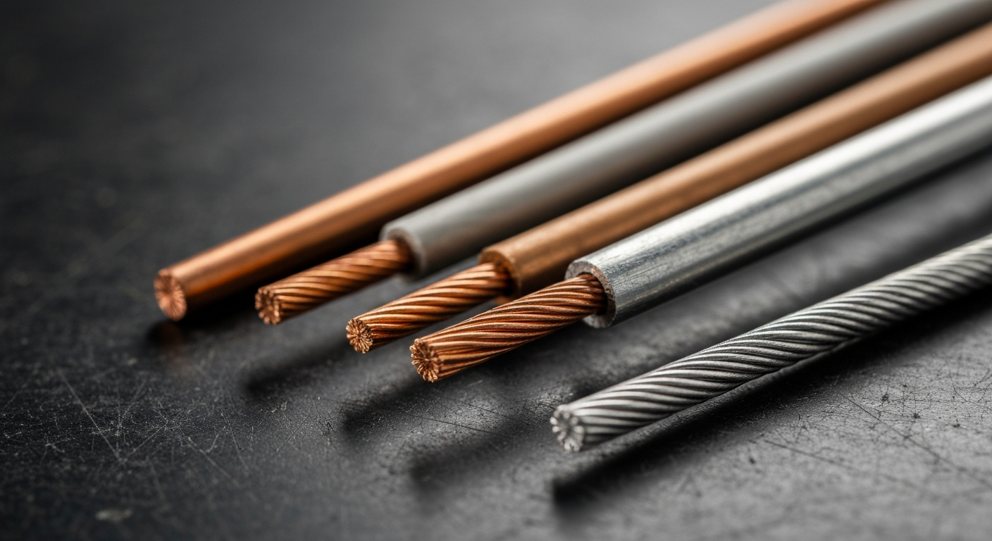
The two most prevalent materials used in the trade are aluminum vs. copper conductors. Copper is the benchmark for conductivity and is prized for its durability and lower resistance. Aluminum, while having higher resistivity, is lighter and often more cost-effective, making it a common choice for larger feeders and service entrance conductors. The physical form also matters. The debate between solid vs. stranded wire depends on the application: solid wire is rigid and ideal for permanent installations in conduit, while stranded wire offers flexibility for device connections, appliance cords, and situations involving vibration.
Sizing Conductors: NEC Article 310, Ampacity, and Derating
Properly sizing a conductor is one of the most critical tasks an electrician performs. Undersizing can lead to overheating and fire hazards, while oversizing is inefficient and costly. The definitive guide for this task is NEC Article 310 of the National Electrical Code. This article provides extensive tables and rules governing conductor sizing and their allowable Current-carrying capacity, or Conductor ampacity.
The size of a conductor is typically specified using the American Wire Gauge (AWG) system, where a smaller number indicates a larger wire diameter. For conductors larger than 4/0 AWG, size is measured in Circular mils (CM), which represents the cross-sectional area of the wire.
However, the ampacity values listed in NEC Table 310.16 are not absolute. They must be adjusted based on the conditions of use, a process known as Conductor derating. Factors requiring derating include:
- Ambient Temperature: If the conductor is installed in an environment hotter than the baseline (usually 30°C or 86°F), its ampacity must be reduced.
- Number of Conductors: When more than three current-carrying conductors are bundled in a raceway or cable, the heat they generate cannot dissipate as effectively, requiring a reduction in ampacity.
Failing to perform conductor derating is a common and dangerous code violation. As technology and standards evolve, it’s also important to stay updated on how the 2023 NEC simplifies motor conductor sizing and other complex calculations.
Practical Application: The Voltage Drop Calculation
Beyond ampacity, electricians must also account for voltage drop. As current flows through a conductor, a small amount of voltage is lost due to the wire’s inherent resistance. Excessive voltage drop can cause equipment to malfunction, lights to dim, and motors to run inefficiently. The NEC recommends limiting voltage drop to 3% for branch circuits and 5% total for the feeder and branch circuit combined. Performing a Voltage drop calculation is essential, especially on long runs.
Step-by-Step Voltage Drop Calculation (Single-Phase)
- Identify Variables: You need the conductor’s K-value (approx. 12.9 for copper, 21.2 for aluminum), the current (I) in amps, the one-way length (L) of the circuit in feet, and the conductor’s cross-sectional area in Circular mils (CM).
- Apply the Formula: The formula for single-phase voltage drop is: VD = (2 x K x I x L) / CM.
- Calculate the Result: Plug in your values to find the total voltage drop (VD).
- Determine Percentage Drop: Divide the calculated voltage drop by the source voltage and multiply by 100 to get the percentage. (e.g., (VD / 120V) * 100).
- Verify Compliance: Ensure the percentage is within NEC recommendations. If it’s too high, you must increase the conductor size (which increases the circular mils).
Types of Conductors and Their Roles
In any installation, you’ll encounter various types of conductors, each with a specific purpose defined by code and function.
Service Entrance Conductors and the Ungrounded Conductor
The service entrance conductors are the critical link between the electric utility’s supply and the building’s service disconnecting means. These conductors carry the full load of the structure and must be sized and protected meticulously. Within any circuit, the ungrounded conductor, commonly known as the “hot” wire, is the conductor that carries current to the load under normal operating conditions. It is intentionally maintained at a voltage potential relative to ground.
The Importance of the Bare Grounding Conductor
In contrast, the equipment grounding conductor, which is often a bare grounding conductor (or green-insulated), serves a purely protective role. It is bonded to the non-current-carrying metal parts of equipment and enclosures. In the event of a fault where an ungrounded conductor touches a metal frame, the grounding conductor provides a low-impedance path back to the source, allowing the overcurrent protection device (breaker or fuse) to trip instantaneously and clear the fault, preventing electric shock.
A Look at Common Wire Types like THHN Wire
The designation of a wire, such as THHN wire, tells an electrician a great deal about its properties. THHN stands for Thermoplastic High Heat-resistant Nylon-coated. This designation indicates its insulation type, temperature rating (90°C in dry locations), and outer jacket material. This is one of the most common wire types used in commercial and industrial construction inside conduit. Understanding these designations is crucial, especially when considering alternative materials like copper-clad aluminum conductors for specific applications.
The Role of Insulators: Dielectric Strength and Resistance
If conductors are the highways for electricity, insulators are the guardrails, medians, and retaining walls. An insulator is a material with very high electrical resistivity that prevents the flow of current. The effectiveness of an insulator is measured by its Dielectric strength—its ability to withstand a high voltage without breaking down and allowing current to pass through. Materials like PVC, rubber, glass, and porcelain are excellent insulators.
In the field, electricians test the quality of insulation using a megohmmeter to measure Insulation resistance. This test applies a DC voltage to the conductors and measures any leakage current through the insulation. A low insulation resistance reading can indicate damaged insulation, moisture intrusion, or contamination, signaling a potential failure point that must be addressed before energizing a circuit. The protection of these materials is also paramount, as electricians must know how open conductor installations are protected from physical damage to maintain system integrity.
Key Takeaways for the Professional Electrician
- The conductor definition is a material with low electrical resistivity, while an insulator has high resistivity.
- Conductor ampacity is determined by NEC Article 310 but must be adjusted through Conductor derating for ambient temperature and conductor bundling.
- Always perform a Voltage drop calculation on long circuit runs to ensure equipment operates correctly.
- The American Wire Gauge (AWG) system and circular mils are the standards for expressing conductor size.
- The ungrounded conductor carries current, while the bare grounding conductor provides a path to clear faults for safety.
- An insulator’s quality is measured by its Dielectric strength and verified in the field with an insulation resistance test.
Master the fundamentals of electrical materials with ExpertCE. Our courses provide the in-depth knowledge you need to stay safe, compliant, and at the top of your field.
Primary Sources & Further Reading
This article references standards and best practices established by the National Fire Protection Association (NFPA). For direct access to the code, please refer to:
Frequently Asked Questions (FAQ)
What is the fundamental conductor meaning in electrical work?
The fundamental conductor meaning is a material, typically a metal like copper or aluminum, that allows electrical current to flow through it with minimal resistance. Its primary purpose is to serve as a pathway to deliver electrical energy from a source to a load. The effectiveness of different conductors is based on their low electrical resistivity, which facilitates the easy movement of electrons.
How does NEC Article 310 affect conductor sizing and conductor ampacity?
NEC Article 310 is the authoritative chapter in the National Electrical Code for conductor sizing. It provides detailed tables listing the maximum allowable Conductor ampacity (current-carrying capacity) for various conductor types, sizes (in American Wire Gauge), and insulation ratings. It also contains the critical rules for Conductor derating, which requires electricians to reduce a conductor’s ampacity based on ambient temperature and the number of current-carrying conductors in a raceway.
What is the difference between an ungrounded conductor and a bare grounding conductor?
An ungrounded conductor (often black, red, or blue) is the “hot” wire that carries current to the load during normal circuit operation. A bare grounding conductor (or green-insulated) is a safety wire that is bonded to the metal frames of equipment. It does not carry current under normal conditions. Its sole purpose is to provide a safe path for fault current to flow back to the source, tripping the breaker and preventing electric shock.
Continuing Education by State
Select your state to view board-approved continuing education courses and requirements:
Disclaimer: The information provided in this educational content has been prepared with care to reflect current regulatory requirements for continuing education. However, licensing rules and regulations can vary by state and are subject to change. While we strive for accuracy, ExpertCE cannot guarantee that all details are complete or up to date at the time of reading. For the most current and authoritative information, always refer directly to your state’s official licensing board or regulatory agency.
NEC®, NFPA 70E®, NFPA 70®, and National Electrical Code® are registered trademarks of the National Fire Protection Association® (NFPA®)
You may also like

Colorado Electrical Licensing Requirements and Reciprocity Guide

Standby Generators in DE: Navigating Coastal Storm Regulations
